<4. Piping>
4-2
IM 11M12A01-04E 11th Edition : Jul. 19, 2017-00
4.1.1 Piping Parts for System 1
Check that the parts listed in Table 4.1 are provided.
Table 4.1 Piping Parts
Equipment Piping location Parts Name Description
Oxygen/
Humidity
Analyzer
Calibration gas inlet Stop valve (L9852CB or G7016XH) recommended by
YOKOGAWA
Nipple * Rc1/4 or 1/4 NPT General parts
Joint for tube
connection
Rc1/4 (1/4NPT) for a 6x4mm
soft tube
General parts
Reference gas inlet (Sealed up) (when piping is required, refer to Section 4.1.3)
Note: Parts with marking * are used when required.
General parts can be found on the local market.
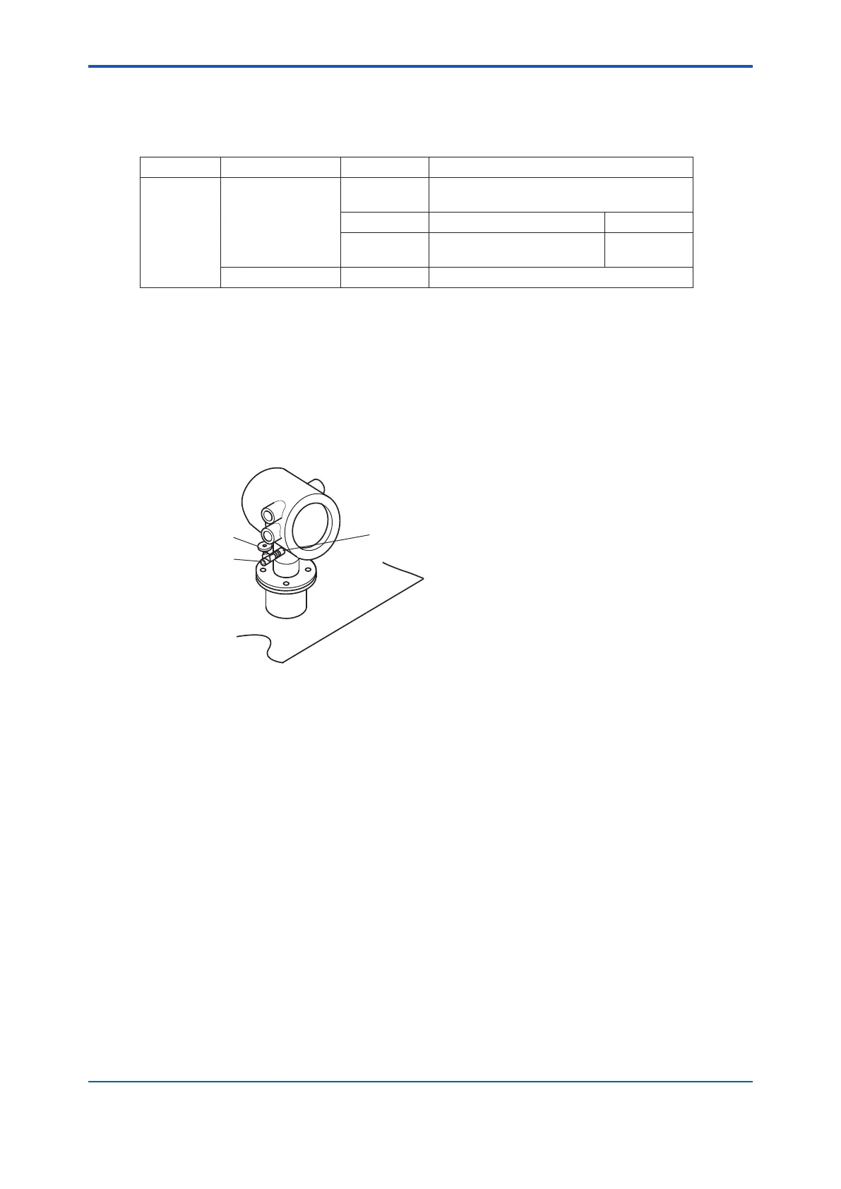
4.1.2 Piping for the Calibration Gas
When carrying out calibration, connect the piping (6(O.D) x 4(I.D.) mm tube) from the standard
gas unit to the calibration gas inlet of the oxygen analyzer. Mount the stop valve (of a quality
specied by YOKOGAWA) through a nipple (found on the local market) as illustrated in Figure
4.2, and mount a joint (also found on the local market) at the stop valve tip. (The stop valve may
be mounted on the equipment when the oxygen analyzer is shipped.)
Note: Mount the stop valve in the vicinity of the equipment.
F4.2E.ai
Stop valve
Tube connection
joint
Nipple
Figure 4.2 Piping for the Calibration Gas Inlet
4.1.3 Piping for the Reference Gas
• Normally, no piping is required for the reference gas inlet when the equipment applies
natural convection for reference gas (models ZR202G-----C). Leave the plug as it is.
If the air around the probe is polluted and the necessary oxygen concentration (21 vol%O
2
)
cannot be obtained, make instrument air piping as in Section 4.2, System 2.
• When the equipment uses instrument air for the reference gas, piping is required as
described in Section 4.2, System 2 (models ZR202G-----E or P).
4.2 Piping for System 2
Piping in System 2 is illustrated in Figure 4.3.

 Loading...


