<5. Wiring>
5-4
IM 11M12A01-04E 11th Edition : Jul. 19, 2017-00
5.2.1 Cable Specications
Use a 2-core shielded cable for wiring.
5.2.2 Wiring Procedure
(1) M4 screws are used for the terminals. Use crimp-on terminals appropriate for M4 terminal
screws for cable connections. Ensure that the cable shield is connected to the FG terminal
of the equipment.
(2) Be sure to connect (+) and (-) polarities correctly.
CAUTION
• Before opening the cover, loosen the lock screw. If the screw is not loosened rst, the cover
will be improperly engaged to the body, and the terminal box will require replacement. When
opening and closing the cover, remove any sand particles or dust to avoid gouging the
thread.
• After screwing the cover on the equipment body, secure it with the lock screw.
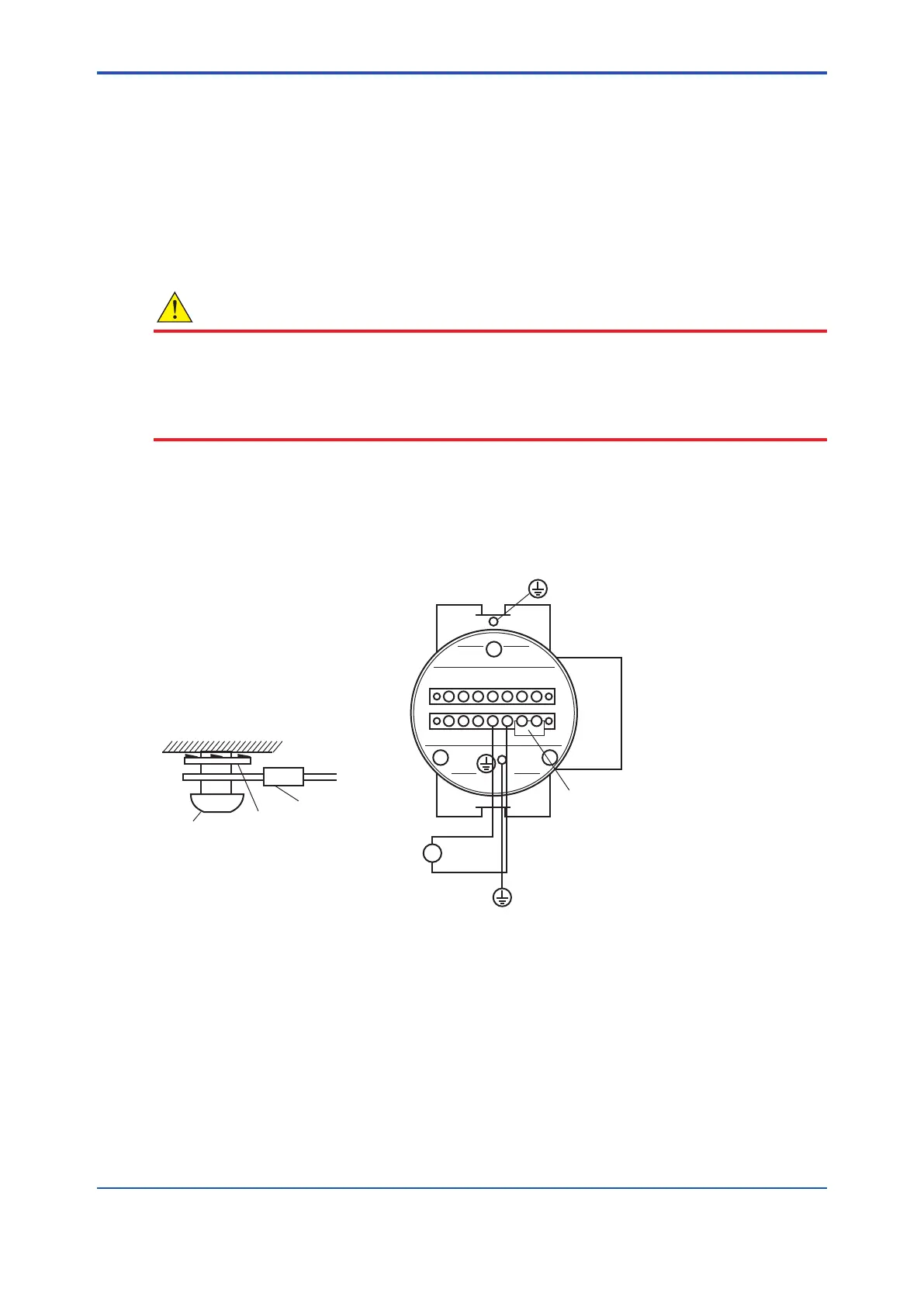
5.3 Wiring Power and Ground Terminals
Wiring for supplying power to the analyzer and grounding the equipment.
1 2 C DO DO
DIDI
1 2
L NFG
+ -
AO
~
100~240VAC
50/60Hz
F5.5E.ai
Jumper plate
Grounding to the earth terminal
on the equipment case
Equipment case
Lock washer
Crimp contact of
the grounding line
Grounding
terminal
FGG
Figure 5.5 Power and Grounding Wiring
5.3.1 Wiring for Power Line
Connect the power wiring to the L and N terminals of the equipment. For a three-core cable,
ground one core appropriately. Proceed as follows:
(1) Use a two-core or three-core cable.
(2) M4 screws are used for the terminals. Use crimp-on terminals appropriate for M4 terminal
screws for cable connections.

 Loading...


