<10. Other Functions>
10-24
IM 11M12A01-04E 11th Edition : Jul. 19, 2017-00
10.6.1 Preparation Before Calibration
To operate the ZA8F Flow Setting Unit, prepare for calibration as follows:
(1) Check for a complete closing of the zero gas ow setting valve in the unit and open the
regulator valve for the zero gas cylinder until the secondary pressure is sample gas
pressure plus approx. 50 kPa (or sample gas pressure plus approx. 150 kPa when a check
valve is used, maximum pressure rating is 300 kPa ).
(2) Check that the oxygen concentration of the zero gas and span gas (instrument air 21 vol%
O
2
) in the cylinder is set for the converter.
10.6.2 Operating the Span Gas Flow Setting Valve
The following description is given assuming that instrument air, the same as the reference gas,
is used as the span gas. For more details, see Section 7.11.2, “Manual Calibration,” earlier in this
manual.
(1) When “OPEn” and the “measured oxygen concentration” appear alternately during the span
calibration, open the span gas ow setting valve of the ow setting unit and adjust the ow
rate to 600 ± 60 ml/min.
Loosen the lock nut if the valve shaft has a lock nut, and turn the valve regulator slowly
counterclockwise. To check the ow rate, use the calibration owmeter. If the sample gas
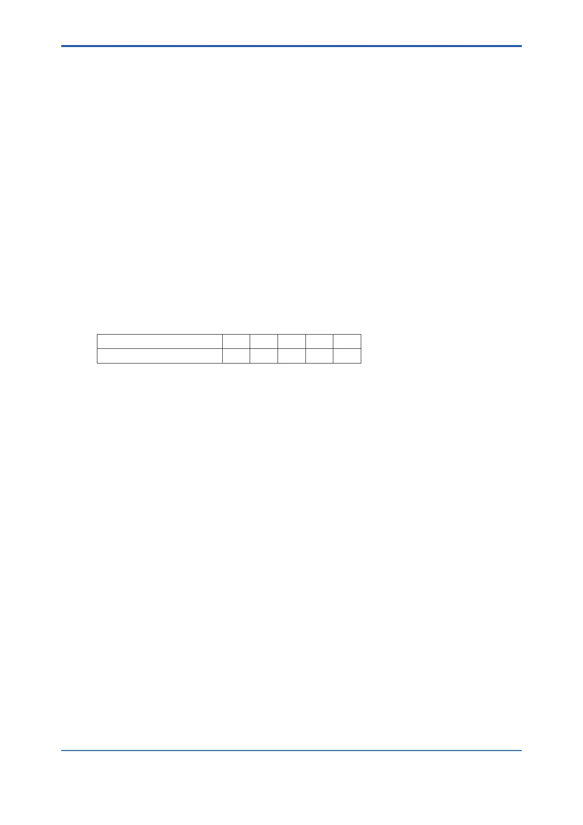
pressure is extremely high, adjust the sample gas pressure to obtain pressures (listed in
Table 10.9) ± 10%.
Table 10.9
Sample gas pressure, (kPa) 50 100 150 200 250
Flow rate, (ml/min) 500 430 380 350 320
(2) Adjust the ow rate. After the measured oxygen concentration has stabilized, touch the
[ENT] key, then all the digits will ash. Touch the [ENT] key again to display “ZEro Y.”
(3) Close the span gas ow setting valve to stop the span gas (air) ow. If the valve shaft has a
lock nut, be sure to tighten the lock nut to prevent any leakage of span gas into the sensor
during measurement.
10.6.3 Operating the Zero Gas Flow Setting Valve
Operate the zero gas ow setting valve during zero calibration in the following procedures:
(1) When the “OPEn” and the “measured oxygen concentration” appear alternately during
calibration, open the zero gas ow setting valve of the ow setting unit and adjust the ow
rate to 600 ± 60 ml/min. To rotate the valve shaft, loosen the lock nut if the valve shaft has a
lock nut and slowly turn it counterclockwise.
(2) To check the ow rate, use an appropriate calibration gas owmeter. If the sample gas
pressure is extremely high, adjust the sample gas pressure to obtain pressures (listed in
Table 10.9) ± 10%.
(3) Adjust the ow rate. After the measured oxygen concentration is stabilized, touch the [ENT]
key, then all the digits will ash. Touch the [ENT] key again to ash “CAL End.”
(4) Close the zero gas ow setting valve to stop the zero gas ow. Be sure to tighten the lock
nut if the valve shaft has a lock nut to prevent any leakage of zero gas into the sensor during
measurement. When the stabilization time elapses, the zero calibration will be complete.
10.6.4 Treatment After Calibration
No special treatment of the instrument is needed after calibration. However, it is recommended
that the pressure regulator for the zero gas cylinders be closed because calibration is not
required so often.

 Loading...


