<4. Piping>
4-4
IM 11M12A01-04E 11th Edition : Jul. 19, 2017-00
F4.8E.ai
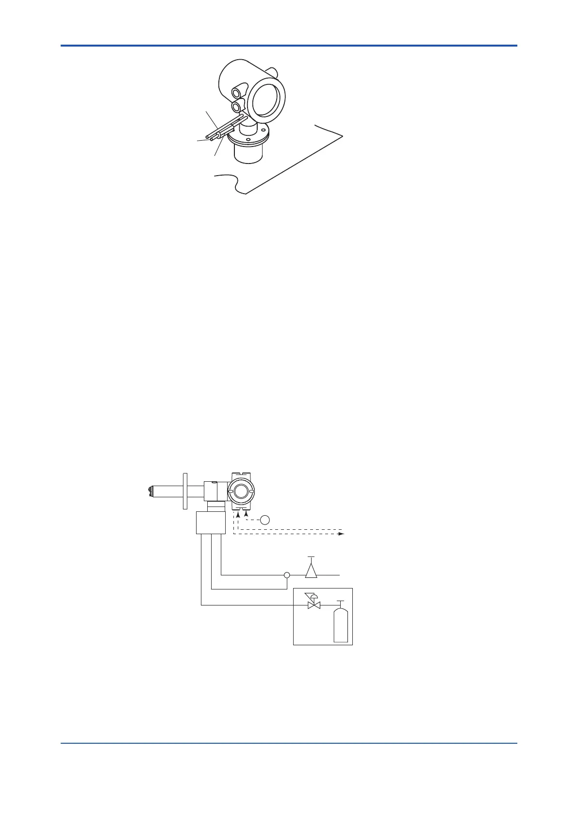
Stop valve or check valve
Piping for the reference gas
6mm (O.D.) by 4mm (I.D.)
stainless steel pipe
Piping for the calibration gas
6mm (O.D.) by 4mm (I.D.)
stainless steel pipe
Figure 4.4 Piping for the Calibration Gas Inlet
4.2.3 Piping for the Reference Gas
Reference gas piping is required between the air source (instrument air) and the ow setting unit,
and between the ow setting unit and the analyzer.
Insert the air set next to the ow setting unit in the piping between the air source and the ow
setting unit.
Use a 6mm (O.D.) x 4mm (I.D.) (or nominal size 1/4 inches) stainless steel pipe between the ow
setting unit and the analyzer.
4.3 Piping for System 3
Piping in System 3 is illustrated in Figure 4.5. In System 3, calibration is automated; however, the
piping is basically the same as that of System 2. Refer to Section 4.2.
Adjust secondary pressure of both the air set and the zero gas regulator so that these two
pressures are approximately the same. The ow rate of zero and span gases (normally
instrument air) are set by a individual needle valve. After installation and wiring, check zero gas
calibration contact output (see Sec. 7.10.2), and adjust zero gas regulator and calibration gas
needle valve so that zero gas ow is within the permitted range. Next check span gas calibration
contact output and adjust air set so that span gas ow is within the permitted range.
~
100 to 240 V AC
Automatic Calibration Unit
Reference gas
Calibration gas (Zero)
Contact input
Analog output, contact output
Digital output (HART)
Air Set
Instrument air
Calibration gas unit case
Pressure
regulator
Zero gas cylinder
ZR202G Integrated type
Zirconia Oxygen/Humidity Analyzer
with automatic calibration
F1.3E.ai
Span gas
ZR20H
Note:
The installation temperature limits range for integrated type analyzer is -20 to 55°C.
Figure 4.5 Piping for System 3

 Loading...


