<3. Installation>
3-8
IM 11M12A01-04E 11th Edition : Jul. 19, 2017-00
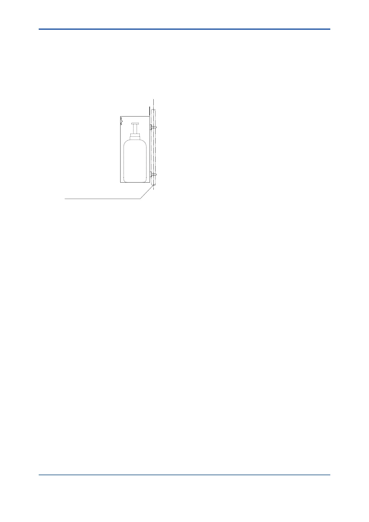
n Mounting
Mount case assembly on a pipe (nominal JIS 50 A) as follows:
(1) Prepare a vertical pipe of sufcient strength (nominal JIS 50A: O.D. 60.5 mm) for mounting
the case assembly. (The sum of the case assembly and the calibration gas cylinder weighs
approximately 4.2 kg.)
(2) Mount the case assembly on the pipe by tightening the nuts with the U-bolt so that the metal
tting is rmly attached to the pipe.
F3-16E.ai
A pipe to be mounted
(nominal JIS 50A : O.D. 60.5 mm)
Figure 3.11 Pipe Mounting
3.5 Insulation Resistance Test
Even if the testing voltage is not so great that it causes dielectric breakdown, testing may cause
deterioration in insulation and a possible safety hazard. Therefore, conduct this test only when it
is necessary.
The applied voltage for this test shall be 500 V DC or less. The voltage shall be applied for as
short a time as practicable to conrm that insulation resistance is 20 MΩ or more.
Remove wiring from the converter and the detector.
1. Remove the jumper plate located between terminal G and the protective grounding terminal.
2. Connect crossover wiring between L and N.
3. Connect an insulation resistance tester (with its power OFF). Connect (+) terminal to the
crossover wiring, and (-) terminal to ground.
4. Turn the insulation resistance tester ON and measure the insulation resistance.
5. After testing, remove the tester and connect a 100 kΩ resistance between the crossover
wiring and ground, to discharge.
6. Testing between the heater terminal and ground, contact output terminal and ground,
analog output/input terminal and the ground can be conducted in the same manner.
7. Although contact input terminals are isolated, insulation resistance test cannot be conducted
because the breakdown voltage of the surge-preventing arrester between the terminal and
ground is low.
8. After conducting all the tests, replace the jumper plate as it was.

 Loading...


