<5. Wiring>
5-3
IM 11M12A01-04E 11th Edition : Jul. 19, 2017-00
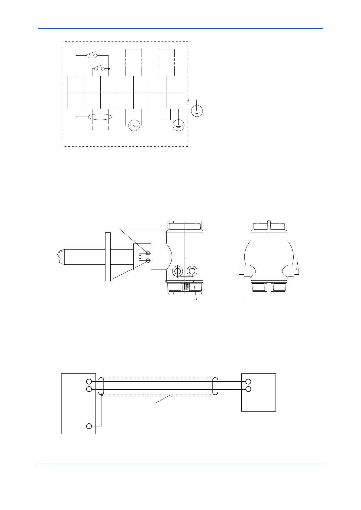
1
DI-1
2
DI-2
3
DI-C
4
DO-1
5
DO-1
6
DO-2
7
DO-2
8
FG
9
AO
(+)
10
AO
(-)
11
L
12
N
13
G
14
FG
F28.EPS
Model ZR202G Integrated type Zirconia Oxygen Analyzer
Contact input 1
Contact output 2
Contact output 1
Analog output
4-20 mA DC
100 to 240 V AC,
50 or 60 Hz
Digital output
Contact input 2
The protective grounding for the analyzer shall be connected either the protective ground terminal
in the equipment or the ground terminal on the case.
Standard regarding grounding: Ground to earth, ground resistance: 100Ω or less.
Figure 5.2 Wiring Connection
5.1.3 Mounting of Cable Gland
For each wiring inlet connection of the equipment, mount the conduit appropriate for the screw
size or a cable gland.
F5.3E.ai
25
4-G1/2,2-1/2NPT etc.
Cable connection port
Cable gland
Rc1/4 or 1/4NPT
Reference gas inlet
Rc1/4 or 1/4NPT
Calibration gas inlet
Figure 5.3 Cable Gland Mounting
5.2 Wiring for Analog Output
This wiring is for transmitting 4 to 20mA DC output signals to a device, e.g. recorder. Maintain the
load resistance including the wiring resistance of 550Ω or less.
+
-
AO(+)
AO(
-)
FG
F5.4E.ai
Shielded cables
Receiver
Figure 5.4 Wiring for Analog Output

 Loading...


