<3. Installation>
3-5
IM 11M12A01-04E 11th Edition : Jul. 19, 2017-00
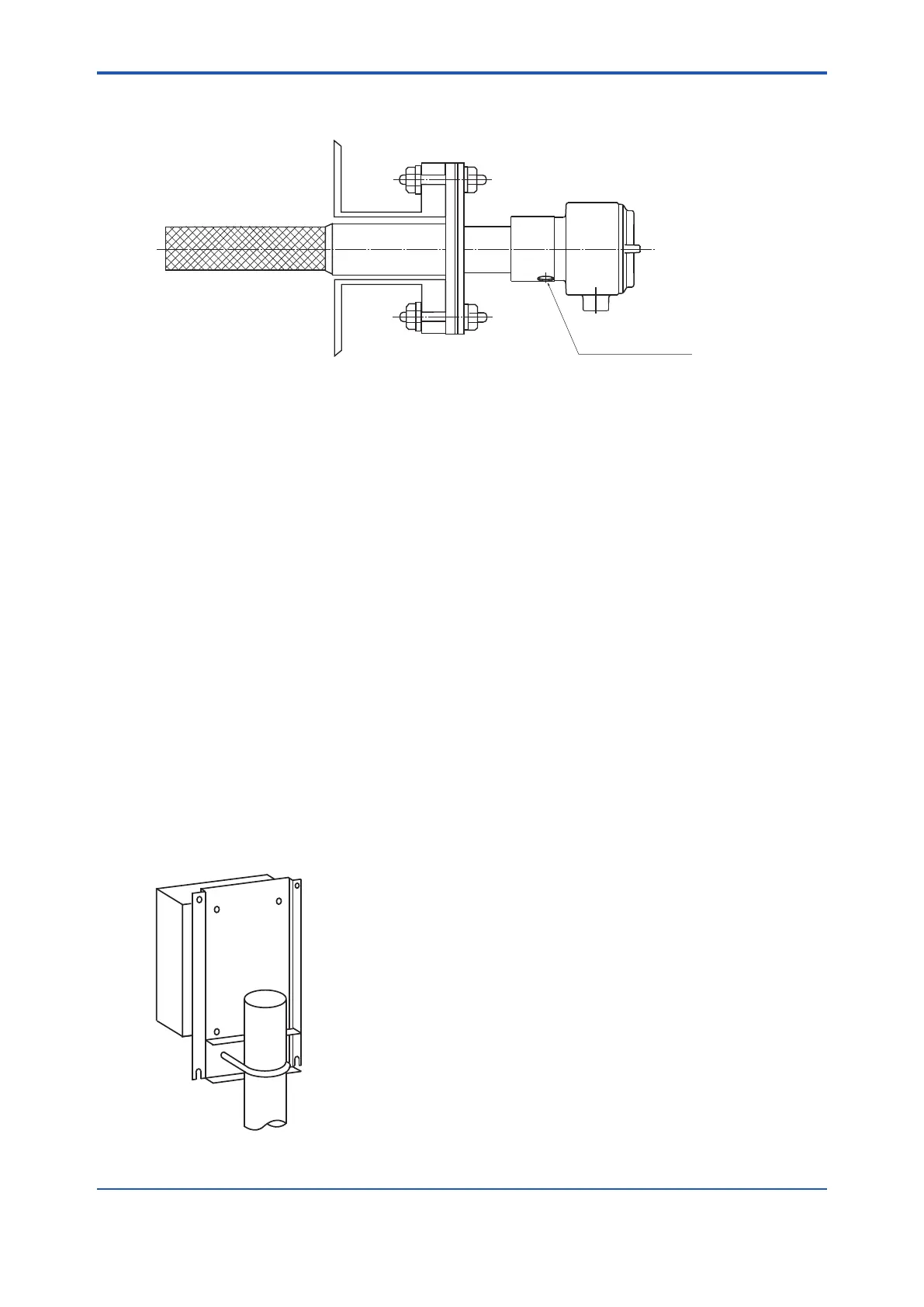
(3) Mount the detector so that the calibration gas inlet and the reference gas inlet face
downward.
F3-2E.ai
Unit : mm
Reference gas inlet
Calibration gas inlet
F3-2E.ai
Unit : mm
Figure 3.6 Installation of the dust lter
3.2 Installation of ZA8F Flow Setting Unit
The following should be taken into consideration:
(1) Easy access to the unit for checking and maintenance work.
(2) Near to the detector and the converter
(3) No corrosive gas.
(4) An ambient temperature of not more than 55°C and little changes of temperature.
(5) No vibration.
(6) Little exposure to rays of the sun or rain.
n Mounting of ZA8F Flow Setting Unit
The ow setting unit can be mounted either on a pipe (nominal JIS 50 A) or on a wall. It should be
positioned vertically so that the owmeter works correctly.
<Pipe Mounting>
(1) Prepare a vertical pipe of sufcient strength (nominal JIS 50A: O.D. 60.5 mm) for mounting
the ow setting unit. (The unit weighs approximately 2 to 3.5 kg.)
(2) Mount the ow setting unit on the pipe by tightening the nuts with the U-bolt so that the metal
tting is rmly attached to the pipe.
F3401E.ai
Figure 3.7 Pipe Mounting

 Loading...


