<7. Startup>
7-14
IM 11M12G01-02EN
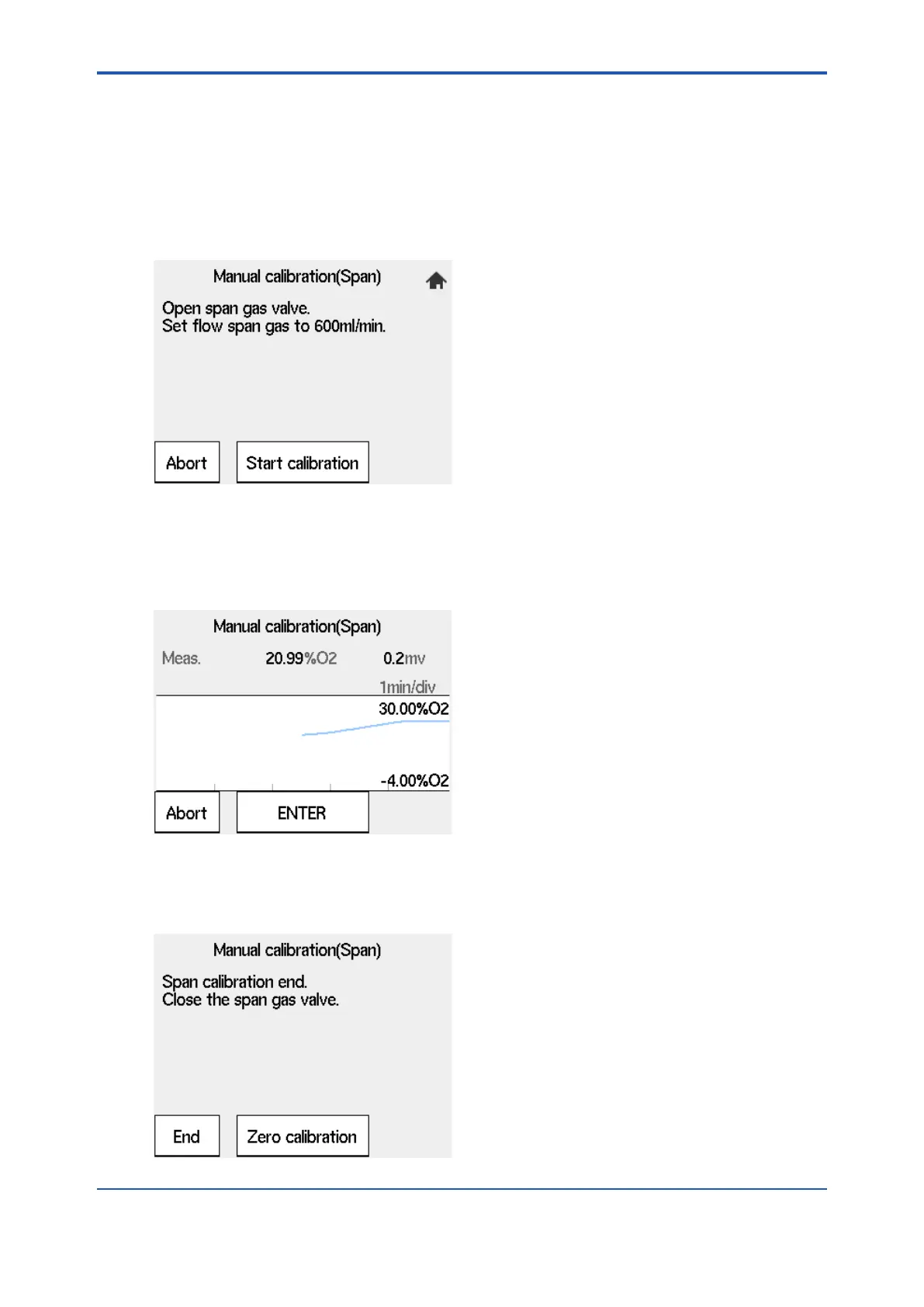
(3) After the message of Figure 7.17 appears, feed the span gas to follow the message. Open
shown in Figure 7.29 then appears. Check that the oxygen concentration for the span gas
in this display coincides with the oxygen concentration in the calibration gas actually used. If
the check results are assumed to be OK, select “Next” in the Manual calibration display.
the lock nut and slowly turn the valve shaft counterclockwise. Flow rate is checked with
Figure 7.17 Span gas Flow Display
(4) Selecting “Start calibration” displays the trend graph of the oxygen concentration being
measured (Fig. 7.18) on screen. Wait for the reading to stabilize around 21% by monitoring
the graph and the sensor electromotive force. At this point, calibration is not yet executed. It
is acceptable for the reading to deviate from 21%.
(The vertical and horizontal scales of the graph are static.)
Figure 7.18 Trend during Span gas calib.
(5) After the measured value has stabilized, press the [Enter]. The screen of Figure 7.19
that the span gas does not leak.
Figure 7.19 Span Calibration Complete
1sh Edition : Mar. 25, 2021-00
 Loading...


