JOHNSON CONTROLS
58
FORM 161.01-OM1
ISSUE DATE: 6/8/2018
SECTION 3 - OPTIVIEW™ CONTROL CENTER FUNCTIONS AND NAVIGATION
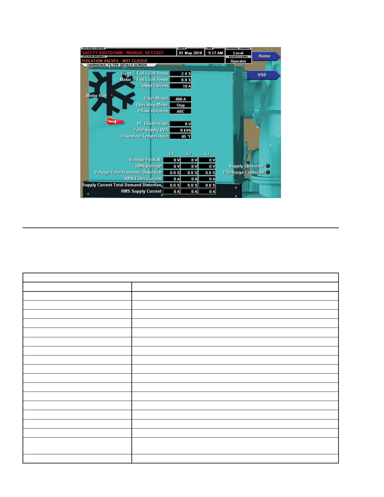
FIGURE 20 - HARMONIC FILTER DETAILS SCREEN
LD26727
This screen displays more detailed parameters associ-
ated with the Harmonic Filter.
DISPLAY ONLY FIELDS
DISPLAY ONLY FIELDS
FIELD/LED NAME DESCRIPTION
Motor Run (LED) Indicates the digital output from the controls is commanding the motor to RUN.
Input % Full Load Amps Displays the current draw as a percentage of the unit Full Load Amps.
Motor % Full Load Amps Displays the current draw as a percentage of the motor Full Load Amps.
Input Current Displays the Input Current to the VSD.
Filter Model Displays the Filter model as reported by the VSD.
Operating Mode Displays Run or Stop.
Phase Rotation Displays rotation sequence of the incoming power.
DC Bus Voltage Displays the DC Bus voltage for the harmonic lter.
Total Supply kVA Displays the supply kVA measured by the VSD.
Baseplate Temperature Displays the highest harmonic lter output inverter baseplate temperature.
Supply Contactor (LED) Indicates the Supply Contactor is energized.
Precharge Contactor (LED) Indicates the harmonic lter DC bus has been pre-charged.
Voltage Peak N- Displays the peak voltage for L1, L2 and L3.
RMS Voltage Displays the RMS voltage for L1, L2 and L3.
Voltage Total Harmonic Distortion Displays the percentage of Harmonic Distortion for L1, L2 and L3.
RMS Filter Current Displays the RMS Filter Current for L1, L2 and L3.
Supply Current Total Demand Distor-
tion
Displays the Supply Current TDD for L1, L2 and L3.
RMS Supply Current Displays the RMS Supply Current for L1, L2 and L3.