JOHNSON CONTROLS
38
FORM 161.01-OM1
ISSUE DATE: 6/8/2018
SECTION 3 - OPTIVIEW™ CONTROL CENTER FUNCTIONS AND NAVIGATION
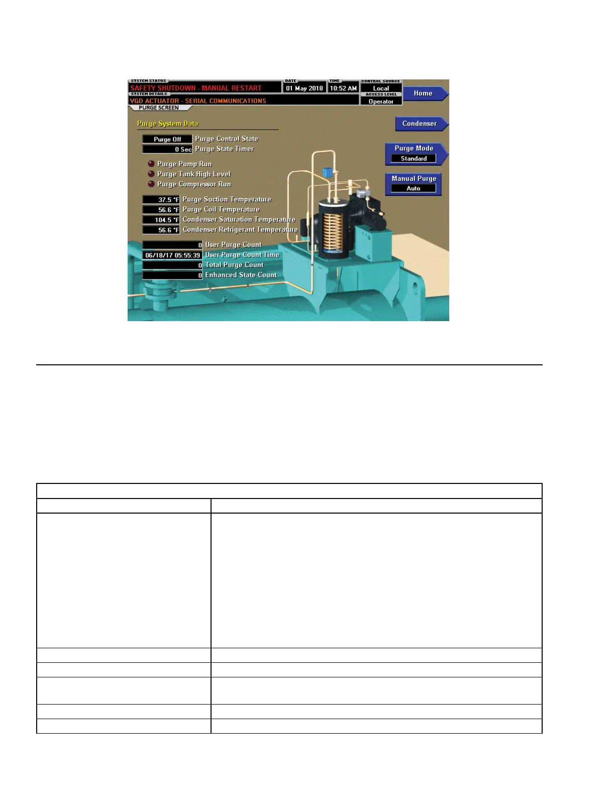
FIGURE 10 - PURGE SCREEN
LD26732
DISPLAY ONLY FIELDS
DISPLAY ONLY FIELDS
FIELD/LED NAME DESCRIPTION
Purge Control State
Indicates the current control state in effect for the purge system.
• Disabled
• Auto Inhibit
• Manual Inhibit
• Purge Off
• Purge On
• Purge Air
• Regen
• Regen Drain
• Equalizing
• Purge Take Drain
Purge State Timer Indicates the current control state currently in effect for the Purge system.
Purge Pump Run (LED) Indicates ON when the Purge Vacuum Pump runs.
Purge Tank High Level (LED)
Indicates ON when the Purge High Level switch is closed indicating that the
Purge Tank is full of refrigerant
Purge Compressor Run (LED) Indicates ON when the Purge Compressor runs.
Purge Suction Temperature Displays the Purge Compressor Suction Temperature.
Low pressure systems such as the YZ chiller operate
at pressures below atmospheric pressure. This means
that any leaks will suck air into the system. Air is non-
condensable and therefore interferes with the refrig-
eration cycle causing high head and poor heat transfer.
The purge system monitors for air in the system and re-
moves it. This screen displays a view of the purge sys-
tem. Setpoints relating to the purge system are shown
on this page as well as the chiller parameters affect-
ing the purge cycle. The YZ purge system monitors the
chiller conditions to diagnose when non-condensables
are present and then remove them from the system.