Smart Connect Single Loop Touch Screen Panel
Doc: GLT-229-7-1 27
Issue: 3
Date: 12/05/2017
The AC Live (L), Earth (E) and Neutral (N) connections are marked on the power supply cage. It is essential that the mains Earth
cable is connected to the PSU’s Earth terminal. The incoming mains cable should be kept separate from the loop cables to help
minimise mains interference.
MAKE SURE ANY SPARE ENTRY HOLES THAT HAVE BEEN OPENED, BUT NOT USED ARE COVERED WITH SUITABLE GROMMETS OR
BLANKING SCREWS
It is advisable to apply power to the panel before connecting any devices, to check for correct operation, and to familiarise yourself
with the fire alarm panels controls.
If a knockout is removed, fill the hole with a suitable cable gland. If any knockout is removed, but subsequently not used, it should
be covered up.
The 230V AC Mains cable must be fed into the enclosure via one of the cable entries at the top right corner of the back box. (Refer
to “Connecting the Mains Power” in Section 6.1).
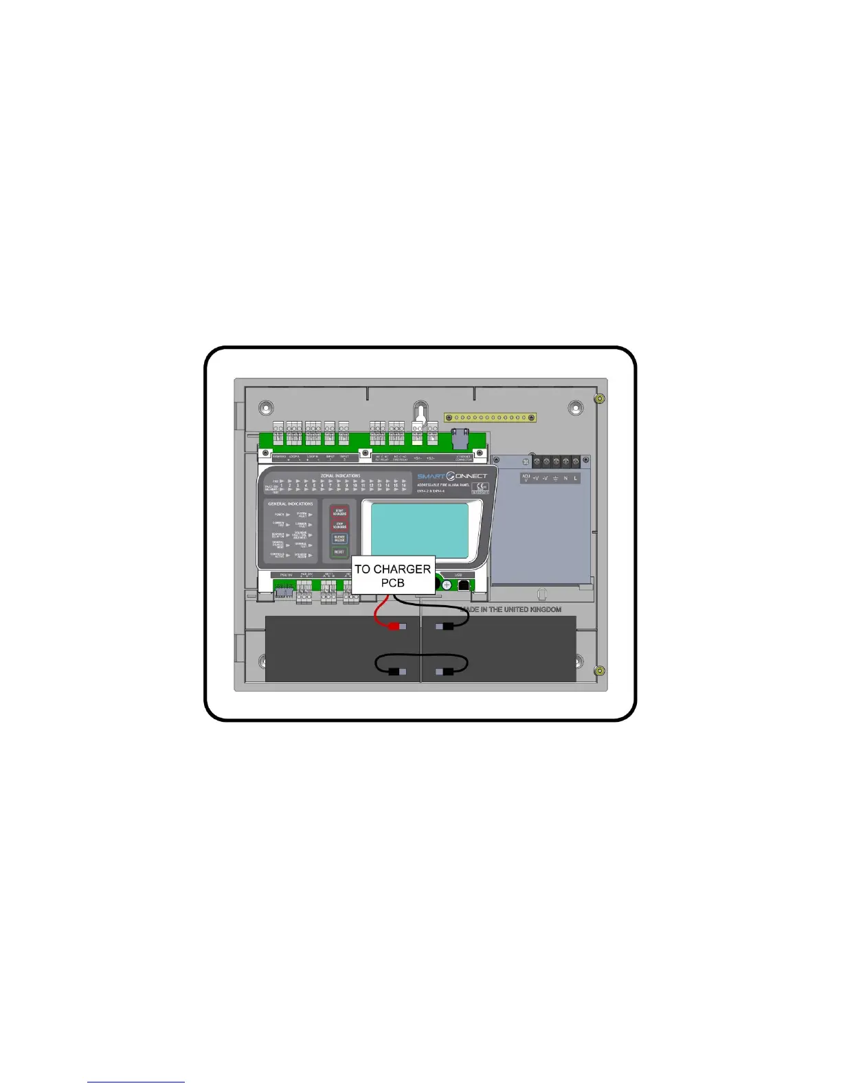
5.7 CONNECTING THE BATTERIES
Figure 3: Battery location and connection details.
To calculate the exact requirement, use the equation in the STANDBY BATTERY REQUIREMENTS section.
The two batteries are wired in series.
The +ve of one battery is connected to the red battery lead.
The –ve of the other battery is connected to the black battery lead.
The –ve of the first battery is connected to the +ve of the second battery using the link wire supplied.
Recommended Battery Types: Powersonic 12V, 7 Ah
Other makes and sizes of battery may be suitable. Calculate the standby requirements to determine the most suitable size of
battery
 Loading...