Smart Connect Single Loop Touch Screen Panel
Doc: GLT-229-7-1 30
Issue: 3
Date: 12/05/2017
6.3 SPECIFIC DEVICE WIRING INSTRUCTIONS
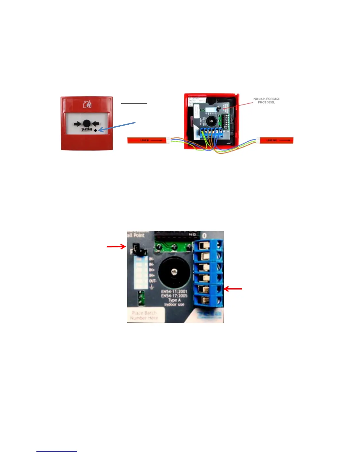
6.3.1 CP3/AD Manual Call Point
The CP3/AD call point has a built in isolator which can be wired in circuit or not used. This is done by means of not wiring to the
negative out terminal on the call point. The following terminals are used for connecting the call point.
2 x Negative in terminals (note if you only connect to the negative in terminals then the isolator is bypassed)
1 x Positive in terminal
1 x Positive out terminal
1 x Negative out terminal (note if used puts the isolator in circuit)
1 x Earth terminal used to connect the cable screen