5.14 Manual Bypass-Switch type S-D-25 and S-D-50
As accessories are manual main switches with bypass function available.
By switching OFF Frequency inverters necessary waiting period before renewed switching on
amounts minimum 90 seconds!
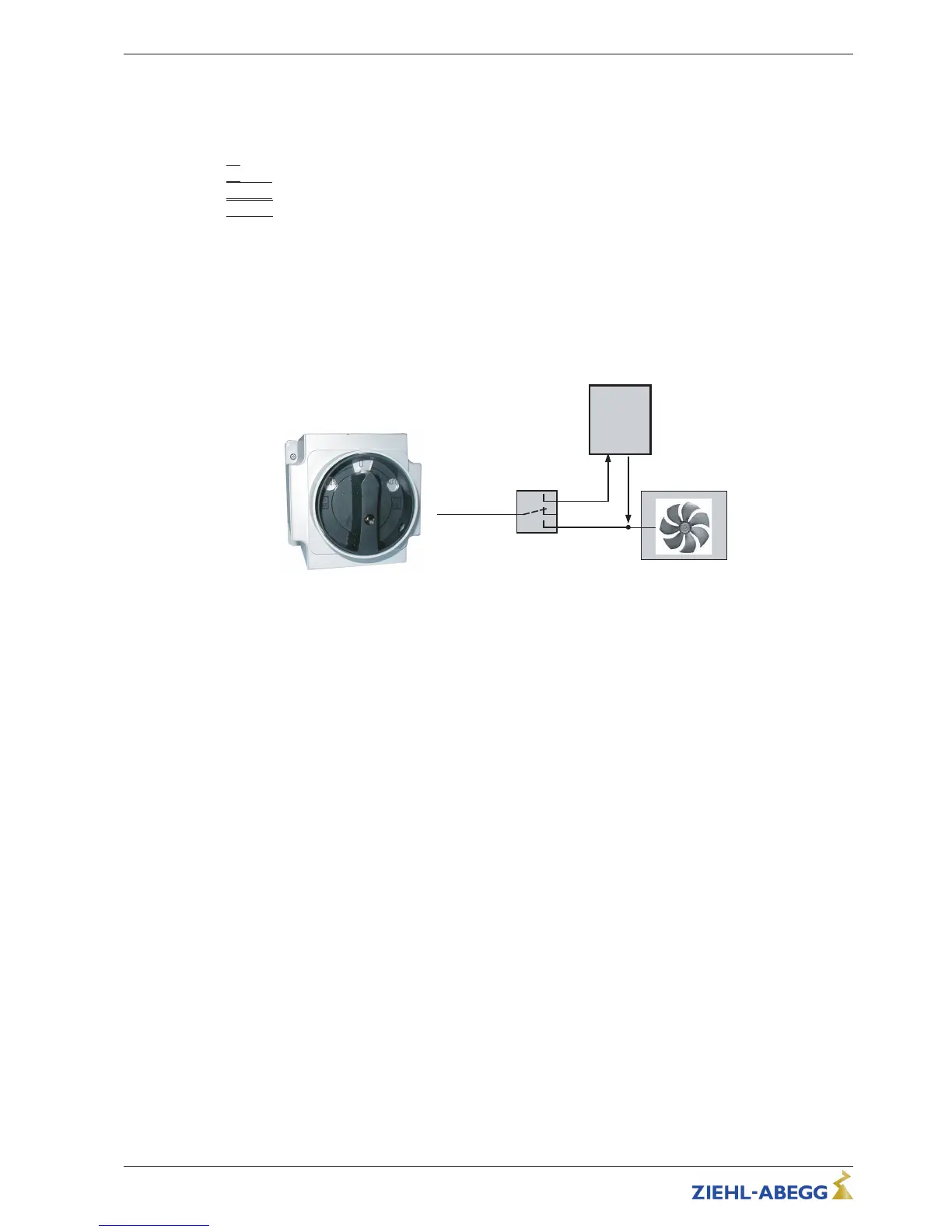
Switch position
•
|
0
|
= Switch OFF supply line (lockable)
•
|
AUTO
|
= Operation Control
•
|
100 %
|
= Operation Bypass (controller without supply)
Technical data
•
Line voltage max. 690 V, 50/60 Hz
•
Rated current
– Type S-D-25 Part.-No. 349035: 25 A
– Type S-D-50 Part.-No. 349040: 50 A
•
Dimensions w x h x d [mm]
– Type S-D-25: 115 x 115 x 163
– Type S-D-50: 135 x 135 x 188
•
Protection class IP65
Manual Bypass-Switch type S-D-25 / S-D-50
5.15 Potential at control voltage connections
The control voltage connections (< 50 V) relate to the joint GND potential (Exception: Relay contacts
are potential free). There is a potential separation between the control voltage connections and the
protective earth. It must be ensured that the maximum external voltage at the control voltage
connections cannot exceed 50 V (between “GND” terminals and “PE” protective earth). If necessary, a
connection to the protective earth potential can be established, install bridge between “GND” terminal
and the “PE” connection (terminal for screening).
Operating Instructions Fcontrol Basic – model series FSDM2.5..50AM Electrical installation
L-BAL-E174-GB 1704 Index 005 Part.-No.
20/49