Fcontrol Basic FSDM...(A)M
L3L2L1
PE
Netz
Line
3 ~ 208...480 V 50/60 Hz
L1 L2 L3
U V W
TB/
TP
TB/
TP
E1 D1 GND 10V 24V
Eingang
Input
0...10 V
0...20 mA
0...100 % PWM
+
4
Digital In 1
Analog In 1
24 V DC Out
10 V DC Out
01
Aus / Ein
Off / On
10V
+
13 14
K1
Kontaktbelastung
Contact rating
max. AC 250 V 2 A
7
M
3 ~
U
V W PE TB
Y/Δ
q
3 ~ Motor
mit eingebauten Thermostatschaltern
with internal thermostats
3
TB
1
J1 E1,1 E1,2
TB
TP
0...20 mA
0...10 V
(10 V PWM)
15...28 V PWM
6
Temperaturfühler
Thermistors
TP =
Thermostatschalter
Thermostats
TB =
N
N
5
UMUN13K2
14.01.2016
2
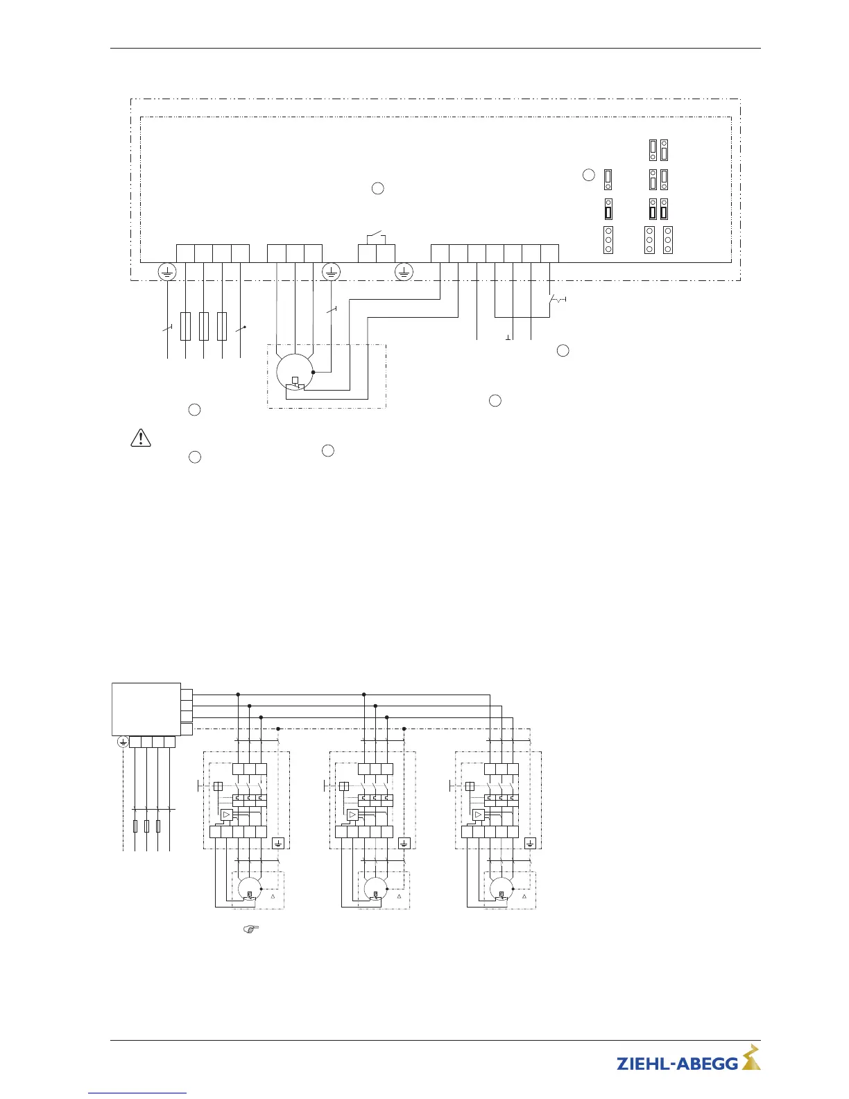
Nicht für IT-System geeignet!
Not suitable for IT-System!
TB/TP In
1 Line 3 ~ 208 V...480 V, 50/60 Hz ("N" - connection only available for FSDM22)
2 Not suitable for IT system!
3 3 ~ Motor with internal thermostats
4 Input: 0...10 V, 0...20 mA, 0...100 % PWM
5 Enable Device Off / On
6 TP = thermistors, TB = thermostats
7 Contact rating max. 2 A / 250 V AC
12.2.1 Connection suggestion for several motors with motor protection units type STDT
•
Full motor protection by switch-off when activating the attached thermostat switches “TB”. Reset after
malfunction by key press.
•
Line protection: A thermal over current sensor and a magnetic short circuit releasing elements are the
parts of the integral line protection. Adjustment to the thermal overcurrent sensor to the max. permissible
current of the connected cable (max. line fuse 80 A).
•
No cut-off if the mains supply is interrupted
Consider max. terminal load
Operating Instructions!
(General example, data for the connection of the controller dependent on the used type of device)
Operating Instructions Fcontrol Basic – model series FSDM2.5..50AM Enclosure
L-BAL-E174-GB 1704 Index 005 Part.-No.
45/49