K1
1 = energized, terminals 13 - 14 bridged
0 = de-energized 13-14 not bridged
Function Status Controller K1
1 = energized
0 = de-energized
Inverting
OFF ON
1K Operation without fault, line supply okay 1 0
2K Fault with indication by relay 0 1
4K Exceed Frequency / Speed > setting “Set Internal3” 1 0
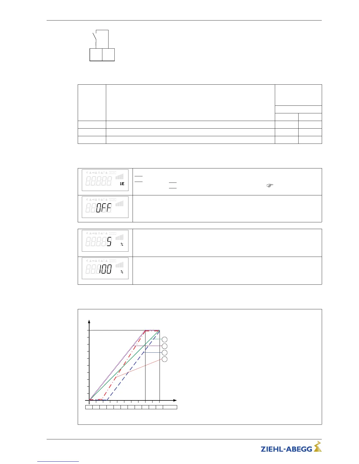
8.5.3 Input “E1”
E1 Function
E1 Function
|
1E
|
(factory setting) = speed setting by external signal (0 - 10 V / PWM).
For settings via
|
1E
|
“E1” operates like “D1” as a digital input (
digital inputs /
function).
E1 Inverting
E1 Inverting
Factory setting inverting to “OFF”.
For control with inverted setting signal switch to “ON” (setting signal: 10 - 0 V).
E1 Min.
E1 Min.
Value of the input signal at which the controller starts at minimum modulation.
Setting range: 0 - 100 %
Factory setting: 5 %
E1 max
E1 max
Value of the input signal at which the maximum modulation of the controller is reached.
Setting range: 0 - 100 %
Factory setting: 100 %
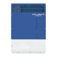
Example for signal adaption
Idealized principle diagrams for setting: “Min. Speed” = 0.0 Hz and “Max. Speed” = 50.0 Hz
F
out
[Hz]
Si E
0 1 2 3 4 5 6 7 8 9 10 0 – 10 V
15.02.2012
v_e1_adjust_i_basic.vsd
1
E1 min. = 0 %, E1 max. = 100 %
50
2
E1 min. = 25 %, E1 max. = 100 %
40
30
20
10
3
E1 min. = 20 %, E1 max. = 80 %
E1 min. = 0 %, E1 max. = 80 %
4
Fout Output frequency
Si E Speed setting signal
Example: “E1 min.” = 20 %
The controller begins only at approx. 20%
higher signal with minimal modulation.
Example: “E1 max.” = 80 %
The modulation rises linear to 100% modu-
lation with 80% setting signal.
Operating Instructions Fcontrol Basic – model series FSDM2.5..50AM Programming
L-BAL-E174-GB 1704 Index 005 Part.-No.
29/49