5.7 Motor protection
Motor protectionis possible by connecting thermostats “TB” (thermal contacts) or thermistors “ TP”
(PTC).
The jumper “J1” in the connection space must be plugged according to the used thermal protectors.
Motor with thermistors “TP”
For motor with thermistors “TP” the jumper “J1” must be plugged at the top.
A maximum of six individual thermistors (DIN 44081 or DIN 44082) may be connected in series to
a single device.
Motor with thermostats “TB”
For motor with thermostats “TB” jumper plugged at bottom (factory setting).
When a connected thermostat or thermistor responds (interruption between the two terminals
“TB/TP”) the device switches off and does not switch back on.
Relais “K1” is de-energized, terminals “13” - “14” interrupted. The internal signal lamp flashes in code
|
15
|
(
Diagnostics / faults).
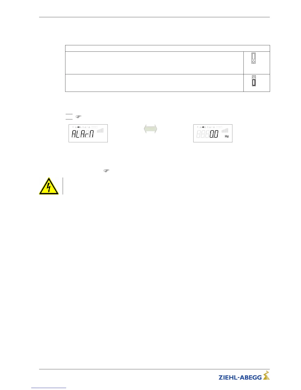
Motor fault
Display actual-value alternates with an
alarm message
Frequency
Possibilities for re-starting after the drive has cooled down terminals “TB/TP” bridged by:
•
By switching the mains voltage off and then on again.
•
Via a digital input for remote control (ON/OFF enable).
•
Function “Reset
”
Menu group “Start”
Danger due to electric current
An outside voltage may never be connected to the terminals “TB/TP” and/or!
5.8 Analog input “E1” for setting fan speed
The device has an analog input for setting the fan speed. Connection “E1” / “GND” (Analog In 1).
The internal jumpers “E1.1” and “E1.2” are factory set in the position for a 0...10 V speed setting
signal.
The appropriate jumper positions must be observed for a 0...20 mA signal or a PWM signal.
Operating Instructions Fcontrol Basic – model series FSDM2.5..50AM Electrical installation
L-BAL-E174-GB 1704 Index 005 Part.-No.
17/49