3D Systems, Inc.
31
p/n: 15-D99, rev. C
6.4 Compressed Air Requirements
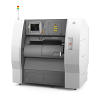
A customer supplied compressed air system must be in place before the DMP Flex 350 is installed.
When installing the compressed air supply line:
• The supply line must reach the DMP system + 5m.
• Route compressed air supply line through the ceiling.
• Locate the drop over the control panel.
• Keep the compressed air line as short as possible to ensure proper pressure.
• Use a minimum of 8 mm tubing.
The connection for the compressed air supply is located on the back of the control panel.
COMPRESSED AIR DMP SYSTEM
Connection type
Flow Rate 50 liters/minute
Supply Pressure Minimum 6 bar (87 psi) - Maximum 10 bar (145 psi)
Quality Class 1 according to ISO 8573 – 1:2010
It is not possible to operate the system with compressed air instead of argon. The oxygen sensors in the safety circuit prohibit
 Loading...
