3D Systems, Inc.
4
p/n: 15-D99, rev. C
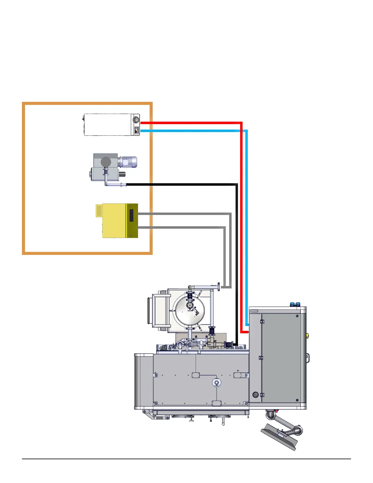
2.2 Split Setup
For a split installation, the blower, vacuum pump and chiller are located in a separate “technical” room. See image below. With
a split installation, the heat and noise generated by the blower, vacuum pump and chiller are eliminated from the working
environment.
distance away from the DMP Flex 350 printer is 10 meters (~400 inches). It is the responsibility of the customer to provide the
additional piping and cabling (both signal and power), that is required for this type of installation. For more information on
these components, please refer to §4.4 Vacuum pump, §4.5 Blower and §4.7 Chiller.
Technical
room
Process Filter
Blower
Vacuum pump
Chiller