Stprmscope
Series
II
Weather
Mapping
Sysiems
WX-PA Instruction Manual
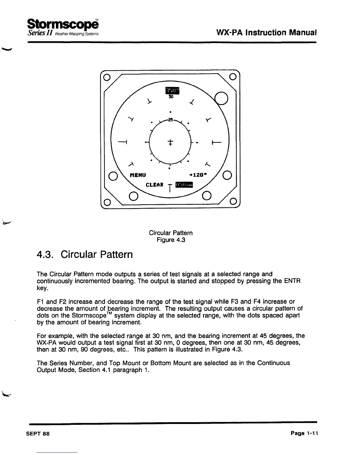
Circular Pattern
Figure 4.3
4.3. Circular Pattern
The Circular Pattern mode outputs a series of test signals at a selected range and
continuously incremented bearing. The output is started and stopped by pressing the
ENTR
key.
F1
and F2 increase and decrease the range of the test signal while F3 and F4 increase or
decrease the amount of bearing increment. The resulting output causes a circular pattern of
dots on the Stormscope
™ system display at the selected range, with the dots spaced apart
by the amount of bearing increment.
For example, with the selected range at 30 nm, and the bearing increment at 45 degrees, the
WX-PA would output a test signal first at 30 nm, 0 degrees, then one at 30 nm, 45 degrees,
then at 30 nm, 90 degrees, etc.. This pattern is illustrated in Figure 4.3.
The Series Number, and Top Mount or Bottom Mount are selected as in the Continuous
Output Mode, Section
4.1
paragraph 1.
SEPT
88
Page
1-11