S~rrnscope
Series
II
Weather
Mapping
Systems
WX-PA Instruction Manual
5.1.4. If the system to be tested is a Series I press "S" once to select "WX7 - 10·, or again to
select "WX10A - 12". For Series II systems, the default series number is correct. If an
incorrect Series number is selected, the data may be displayed on the
stormscope' in an
erratic manner.
5.2. Checking Azimuth
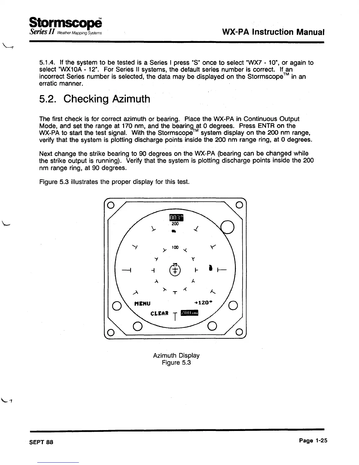
The first check is for correct azimuth or bearing. Place the WX-PA in Continuous Output
Mode, and set the range at 170 nm, and the
bearin~
at 0 degrees. Press ENTR on the
WX-PAto start the test signal. With the Stormscope
M system display on the 200 nm range,
verify that the system is plotting discharge points inside the 200 nm range ring, at 0 degrees.
Next change the strike bearing to 90 degrees on the WX-PA (bearing can be changed while
the strike output is running). Verify that the system is plotting discharge points inside the 200
nm range ring, at 90 degrees.
Figure 5.3 illustrates the proper display for this test.
0
\-
.c
y
100
'<
'i
'(
,
(!)
l-
t/-
.>..
J,.
.A
).
-<
J.....
T
-+120·
T
IIIIIIIIIB
0
0
Azimuth Display
Figure 5.3
SEPT
88
Page
1-25