Alarms
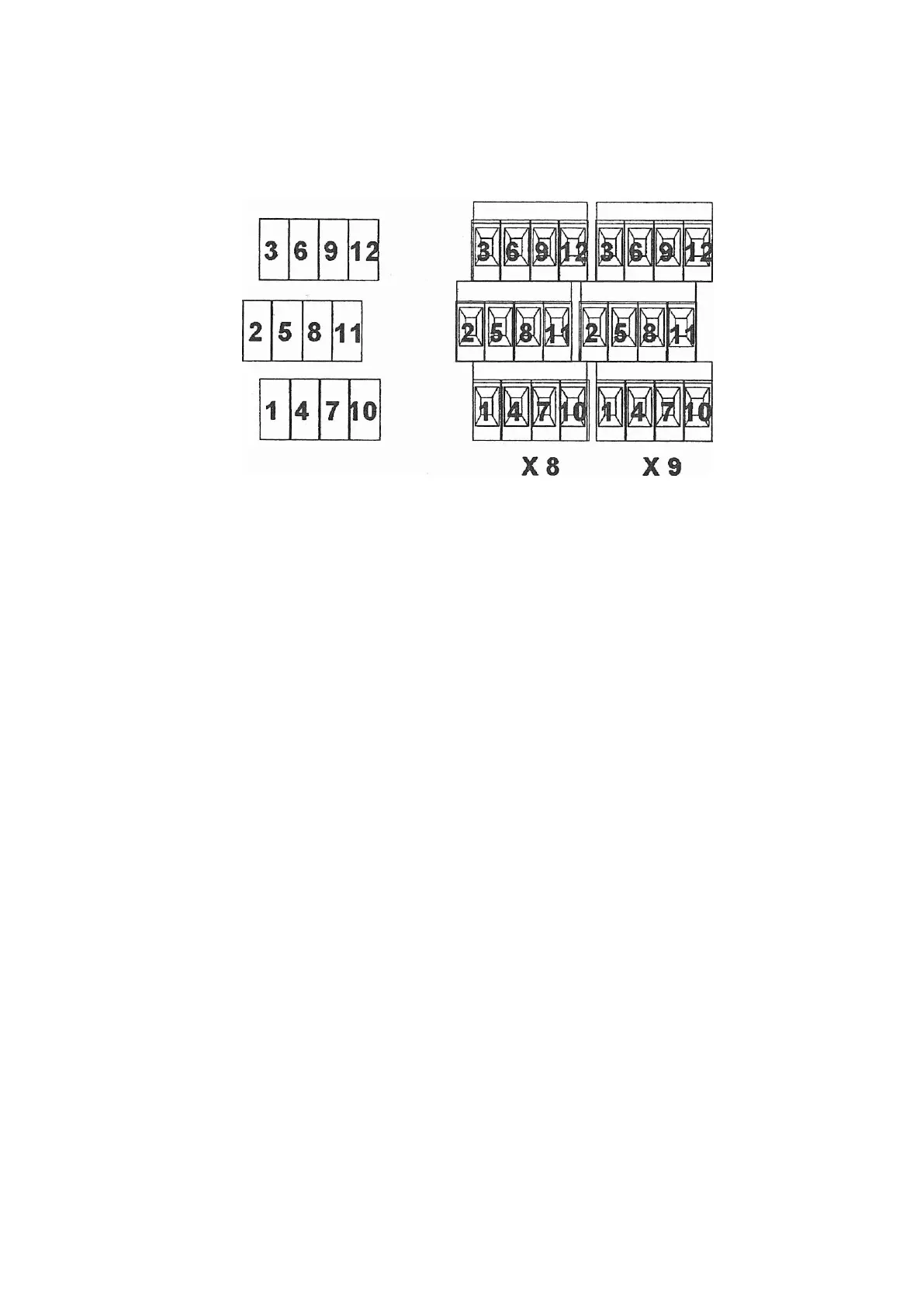
Figure 110 Ports 115-230 V CHEROKEE POWER System
The left side of Figure 110 on page 135 just shows how the alarm contacts, on
the right, are numbered. There are two sets of relay contacts, X8 and X9. Each
column, like 1, 2, 3, shows the contact positions of one relay. From Figure
109 on page 134 and Figure 111 on page 136 you can see that 1, 2, and 3,
are used for relay number 4 in each set and that contact 1, below shown as
X8 - 1, is the common port.
For the normal operation, as seen in the second row of Figure 111 on page
136, contact 2, shown as X8 - 2, is the normally closed port, and contact 3,
shown as X8 - 3, is the normally open port.
135
6/1531-ASP 113 01 Uen J2 2008-07-17