Measurement Methods
2CMC48001M0201 85 A43/A44
Revision: C User Manual
The following illustration shows a vector diagram for resistive, inductive and ca-
A load that consumes both reactive and active energy can be divided into active
and reactive components. The angle between the apparent power (U*I) vector and
the active power component is described as phase displacement angle or power
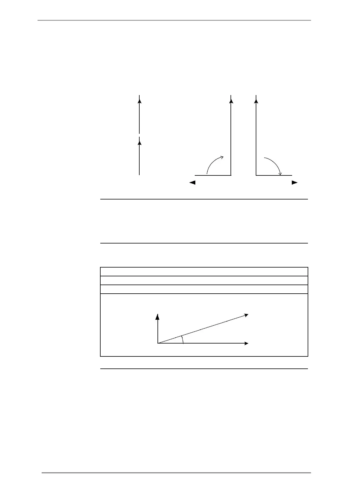
The following illustration shows a vector diagram for a load with an active and a
Active power = P = U x I x cos (unit W)
Reactive power = Q = U x I x sin (unit var)
Apparent power = S = U x I (unit VA)
The type of load can be represented geometrically by for quadrants. In the first
quadrant the load is inductive and active and energy is imported (energy is deliv-
ered from the utility to the customer). In the second quadrant the load is capacitive
and active energy is exported and reactive energy is imported. In the third quad-
rant the load is inductive and active and reactive energy is exported. In the last
quadrant the load is capacitive and active energy is imported and reactive
energy exported.