Communication with Modbus
A43/A44 134 2CMC48001M0201
User Manual Revision: C
Third highest/lowest value during the demand period
The Capture time register shows the date and time when the minimum or
maximum value for this entry occurred.
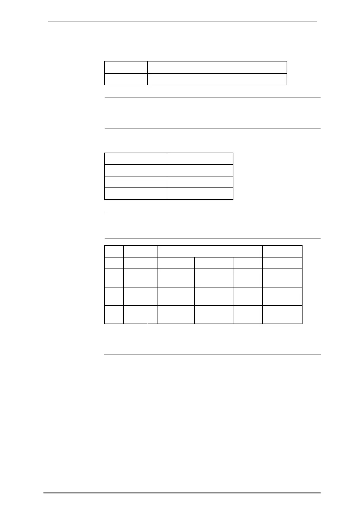
The status register shows the status for a value stored at a given timestamp.
Possible values are shown in the table below:
The following table shows the relation between stored values and channels in data
9.7.1 Reading Demand
General Readout of demand is controlled by the Entry number register or Date/Time
register. Entry number 0 is used for current demand, that is the pending period,
and entry numbers equal or bigger than 1 are used for historic demand periods.
After writing to any of those registers, the values of all channels for the given
entry number or date/time are available in the registers of data block 1 to 7,
together with status and timestamp information.
In the data blocks, the registers Quantity, Level, Data type and Scaler provide
further information about the data stored in each channel. To get the next block of
demand values, write the value 1 to the Get next entry register, and then read again
from the registers in the data blocks.