Communication with Modbus
2CMC48001M0201 133 A43/A44
Revision: C User Manual
Structure of
the data blocks
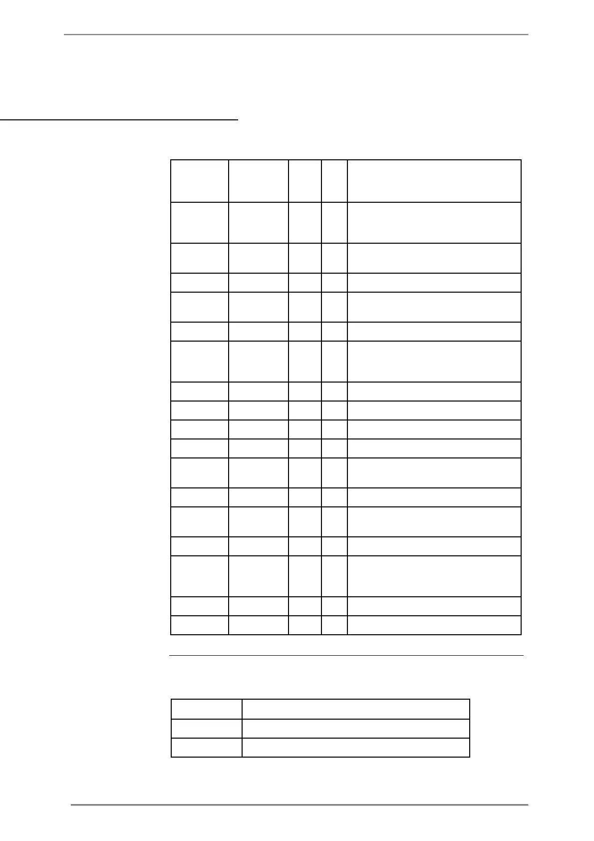
The following table describes the structure of the data blocks:
Date and time for the end if this period, i.e.
when this entry was stored. (Date/Time
OBIS code for the quantity monitored in
Demand level for channel 1.
Data type for quantity monitored in
Scaler for quantity monitored in channel 1.
Date and time when the minimum or
maximum occurred for the quantity
Status for quantity monitored in channel 1.
Value for quantity monitored in channel 1.
OBIS code for the quantity monitored in
Demand level for channel 8.
Data type for quantity monitored in
Scaler for quantity monitored in channel 8.
Date and time when the minimum or
maximum occur ed for the quantity
Status for quantity monitored in channel 8.
Value for quantity monitored in channel 8.
Level register The Level register shows which demand level is configured for this channel. Possible
values are shown in the table below:
Highest/Lowest value during the demand period
Second highest/lowest value during the demand period