Communication with Modbus
A43/A44 136 2CMC48001M0201
User Manual Revision: C
9.8 Event logs
Mapping table
Header and data
block
Note – Before you can use the information in this chapter you must be familiar with
and understand the information and the concepts described in “Historical Data” on
page - 114.
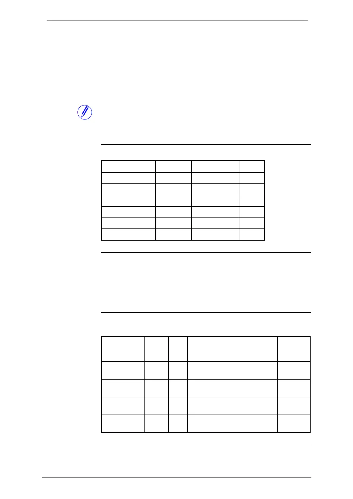
The following table shows an overview of the mapping table:
There is one pair of header and data block for each log type, located in the
registers listed in the mapping table above. In the tables showing the structure
of the header and data block below the register numbers are valid for the
System log. However the headers and data blocks for all log types share the
same structure, so the tables are applicable for all log types if the register
numbers are exchanged to correct values.
Structure of
the header
The following table describes the header:
Write value 1 to this register to load
the next block of log entries
Write to this register to choose an
entry number to start reading from
Write to this register to choose a
date/time to start reading from
Write to this register to choose the