150 Optional I/O extension modules
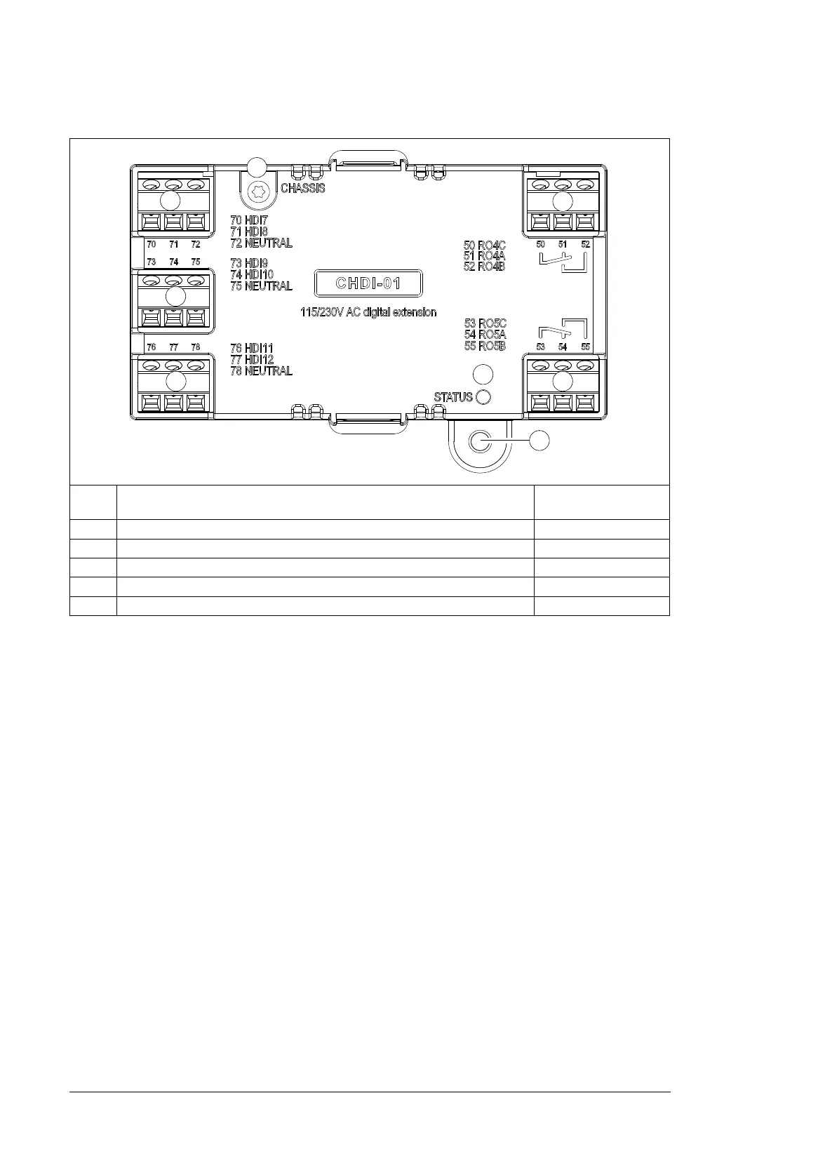
Layout
Mechanical installation
Necessary tools and instructions
• Screwdriver and a set of suitable bits.
Unpacking and checking the delivery
1. Open the option package.
2. Make sure that the package contains:
• CHDI-01 high voltage digital extension module
• mounting screw.
3. Make sure that there are no signs of damage.
Installing the module
See chapter Installing option modules on page 77.
Item Description Additional
information
1 Grounding screw -
2 Hole for mounting screw -
3 3-pin terminal blocks for relay outputs Page 151
4 3-pin terminal block for 115/230 V inputs Page 151
6 Diagnostic LED Page 153

 Loading...


