26 Operation principle and hardware description
Single-line circuit diagram of the drive
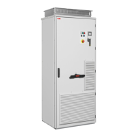
General information on the cabinet layout
Q1 Switch-disconnector
Q2 Optional line contactor (+F250)
T21 Auxiliary voltage transformer supplying 24 V and 230/115 V control voltage for, eg, cabinet fan(s),
control devices and I/O extension adapter module.
T1 Drive module with common mode filter
R12 Optional du/dt filter (+E205)
IP42 IP54
UL Type 1 Filtered
UL Type 12

 Loading...