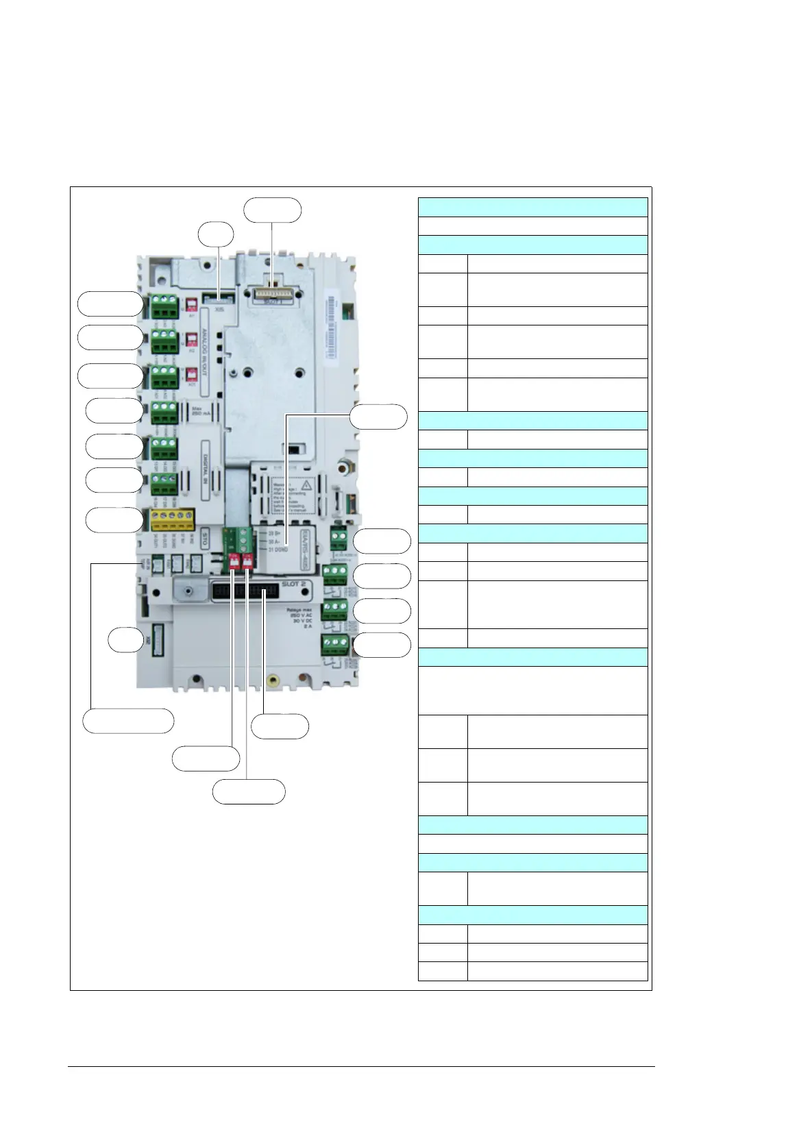
SLOT 1
Option slot 1 (fieldbus adapter modules)
ANALOG IN/OUT
1…3 Analog input 1
AI1 Current/Voltage selection switch
for analog input 1
4…6 Analog input 2
AI2 Current/Voltage selection switch
for analog input 2
7…9 Analog outputs
AO1 Current/Voltage selection switch
for analog output 1
10…12 Auxiliary voltage output
DIGITAL IN
13…18 Digital inputs
STO
34…38 Safe torque off connection
FAN2 Internal fan 2 connection
FAN1 Internal fan 1 connection
X12 Panel port (control panel
connection, wired at the factory
to the control panel)
X15 Reserved to internal use.
SLOT 3
Embedded EIA/R5-485 fieldbus module
(CEIA-01) is installed on SLOT 3 as
standard.
BIAS
S101
Bias resistor switch
TERM
S100
End termination switch
29…31 Connection terminals of the
CEIA-01
SLOT 2
Option slot 2 (I/O extension modules)
40, 41 24 V AC/DC external power
input
RO1 … R03
19…21 Relay output 1 (RO1)
22…24 Relay output 2 (RO2)
25…27 Relay output 3 (RO3)
4…6, AI2
7…9, AO1
10…12
13…15
1…3, AI1
16…18
X12
X15
SLOT 1
FAN 2, FAN 1
34…38
40, 41
19…21
22…24
25…27
SLOT 2
BIAS S101
TERM S100
SLOT 3

 Loading...


