Operation principle and hardware description 29
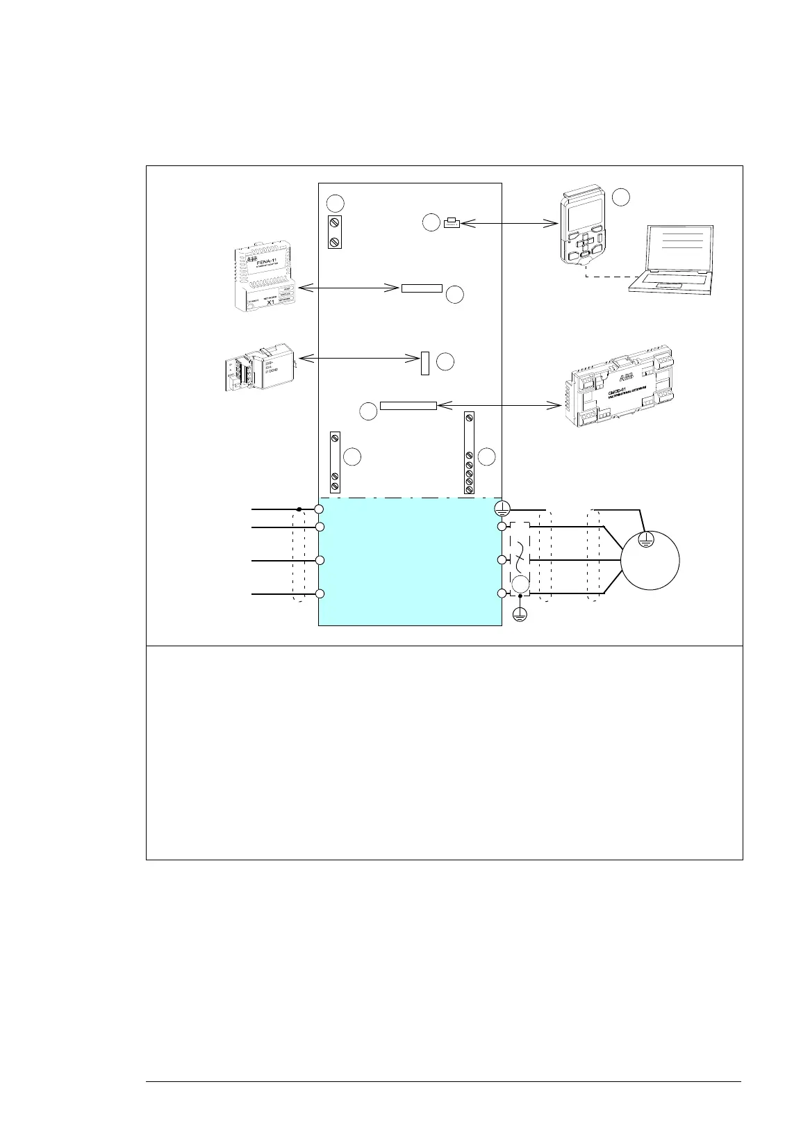
Overview of power and control connections
The diagram shows the power connections and control interfaces of the drive.
1 Option slot 1 for optional fieldbus adapter modules
2 Option slot 2 for optional I/O extension modules
3 Option slot 3 for optional embedded fieldbus adapter modules
4 Panel port
5 I/O terminal blocks. See section Layout on page 80 and section Default I/O connection diagram on
page 81.
6 Control panel, see page 32.
7 Connection terminals for options, see page 30.
8 Additional terminal block X504 for control cable connections to the control unit (option +L504), see
page 34.
9du/dt (option +E205), see page 33.
L1
L2
L3
PE
U2
V2
W2
M 3 ~
L1
L2
L3
PE
. . .
SLOT 2
SLOT 3
SLOT 1
..........
..........
..........
..........
..........
..........
..........
..........
4
3
2
1
...
5
6
. . .
7 8
9
X12

 Loading...


