AO2000 CONTINUOUS GAS ANALYZERS | OI/AO2000-EN REV. B 119
Requisite material
The required system bus cables, T-joints and terminating resistors are sup-
plied per the order.
ATTENTION
For system bus connections use only the yellow system bus cables,
T-joints and terminating resistors. Do not use the violet connectors as
they are only for Modbus connections.
The modules should never be interconnected without using T-joints and
terminating resistors.
System bus connection
1 Place a T-joint on the system bus connection (designated "BUS") of each
module (electronics and analyzer).
2 Connect the T-joints with the system bus cables.
3 Place a terminating resistor on the open ends of each T-piece.
Extension of the system bus cable
Note the following information if using other than the standard system bus
cables and plugs to extend the system bus:
• A shielded cable with twisted pairs and the following specifications is to
be used as an extension cable.
Number and section of
conductors
2 x 2 x 0.25 mm
2
Inductance approx. 0.67 mH/km
Impedance approx. 80 Ω
Coupling (1 kHz) approx. 300 pF/100 m
Operating capacitance Conductor–conductor approx. 120 nF/km,
Conductor–shield approx. 160 nF/km
• For EMC purposes route the system bus cable via metal connection
boxes with metallic cable threaded connections. Connect the shield to
the threaded connections. Connect the unused wires in the 4-conductor
extension cable in the connection box to a PE clamp.
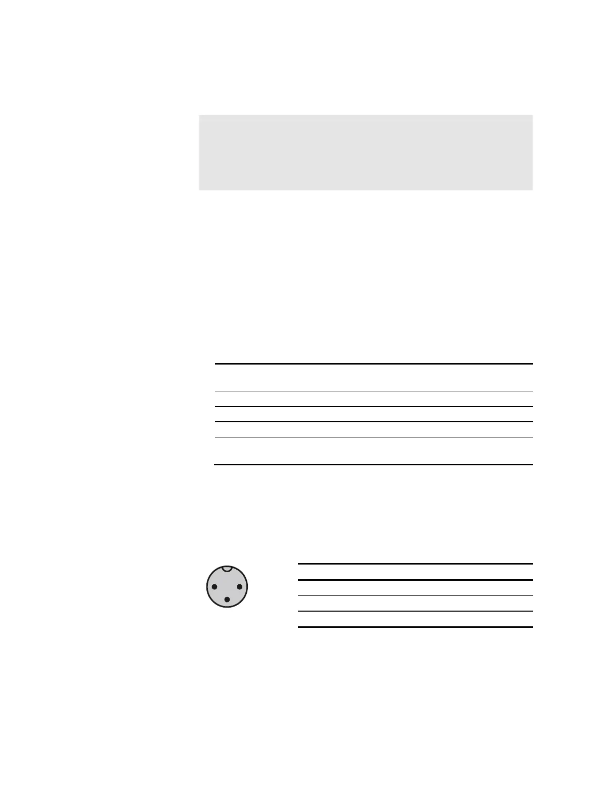
System bus plug layout
(Seen from pin side of cable plug)
2
1
Pin Wire color Signal
1 green System bus LOW
2 brown System bus HIGH
3 white System bus GROUND

 Loading...


