AO2000 CONTINUOUS GAS ANALYZERS | OI/AO2000-EN REV. B 107
Connecting the electrical leads
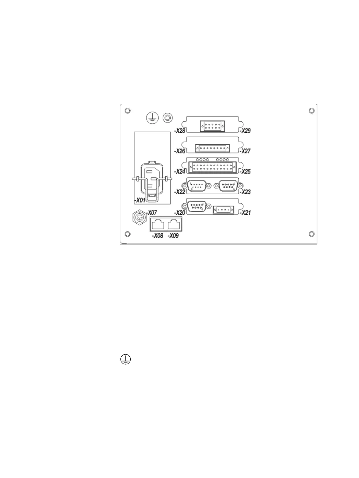
Electronics module connection diagram
Electronics module connection diagram
-X01
Power supply connection (see page 124)
-X07
System bus connection (see page 118)
-X08, -X09 Ethernet 10/100/1000BASE-T connection
-X20 to -X29 I/O Modules (5 slots), options:
– Profibus module (see page 108)
– Modbus module (see page 109)
– 2-way analog output module (see page 110)
– 4-way analog output module (see page 110)
– 4-way analog input module (see page 111)
– Digital I/O module (see page 112)
Potential compensation connection (see page 124)
The connection diagram shows an example for the equipment of the elec-
tronics module with I/O modules.

 Loading...


