1
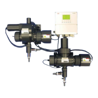
Table 1.1 AV400 Series Dissolved Organics Monitor Options
rebmuNledoMrezylanArezylanAfonoitpircseDArosneSBrosneS
014VAegnaRwoLtupnIelgniS0010237–
114VAegnaRwoLtupnIlauD00102370010237
214VAegnaRhgiHdnawoLtupnIlauD00102370020237
024VAegnaRhgiHtupnIelgniS0020237–
224VAegnaRhgiHtupnIlauD00202370020237
CONTENTS
1 INTRODUCTION .............................................................. 2
1.1 Introduction .............................................................. 2
1.2 Principle of Operation................................................ 2
1.3 AV400 Series Systems .............................................. 2
2 OPERATION ..................................................................... 3
2.1 Powering Up the Monitor .......................................... 3
2.2 Displays and Controls ............................................... 3
2.2.1 Membrane Key Functions ............................ 3
2.3 Operating Page ......................................................... 6
2.3.1 Single Input Dissolved Organics ................... 6
2.3.2 Dual Input Dissolved Organics ..................... 7
2.3.3 Wash Function ............................................. 8
3 OPERATOR VIEWS ......................................................... 9
3.1 View Set Points ......................................................... 9
3.2 View Outputs .......................................................... 10
3.3 View Hardware ....................................................... 10
3.4 View Software ......................................................... 11
3.5 View Clock .............................................................. 11
3.6 View Logbook ......................................................... 12
4 SETUP ............................................................................ 14
4.1 Sensor Calibration Standard Solutions .................... 14
4.1.1 Zero Standard Solution .............................. 14
4.1.2 Span Standard Solution ............................. 14
4.1.3 Calibration Checks .................................... 14
4.2 Sensor Calibration .................................................. 15
5 PROGRAMMING ........................................................... 17
5.1 Security Code ......................................................... 17
5.2 Configure Display .................................................... 18
5.3 Configure Sensors .................................................. 19
5.4 Configure Alarms .................................................... 21
5.5.1 Wash Cycle Configuration (applicable
only to Alarm 3) .......................................... 23
5.5 Configure Outputs .................................................. 25
5.6 Configure Clock ...................................................... 26
5.7 Configure Logbook ................................................. 27
5.8 Configure Security .................................................. 27
5.9 Test Outputs and Maintenance ............................... 28
6INSTALLATION .............................................................. 32
6.1 Siting Requirements ................................................ 32
6.1.1 Transmitter................................................. 32
6.1.2 Sensor ....................................................... 32
6.2 Mounting the Transmitter ........................................ 33
6.3 Installing the Sensor ................................................ 34
6.4 Installing the Optional De-bubbler ........................... 36
6.5 Electrical Connections ............................................. 38
6.5.1 Relay Contact Protection and Interference
Suppression............................................... 39
6.5.2 Cable Entry Knockouts .............................. 40
6.5.3 Access to Terminals ................................... 41
6.5.4 Connections .............................................. 42
7 CALIBRATION ............................................................... 43
7.1 Factory Settings ...................................................... 43
8 SENSOR MAINTENANCE ............................................. 50
8.1 Scheduled Maintenance ......................................... 50
8.2 Cleaning the Sensor ................................................ 50
8.2.1 Dismantling and Cleaning .......................... 50
8.3 Replacing the Emitter and Receiver Modules .......... 55
8.4. Adjusting the Emitter Brightness ............................ 55
9 DIAGNOSTICS ............................................................... 56
9.1 Status Messages .................................................... 56
9.2 Unstable or Erratic Readings ................................... 56
10 SPARES ....................................................................... 57
SPECIFICATION .................................................................. 58
APPENDIX A REPLACING A 7320 TRANSMITTER
WITH AN AV400 .................................................................. 60