3
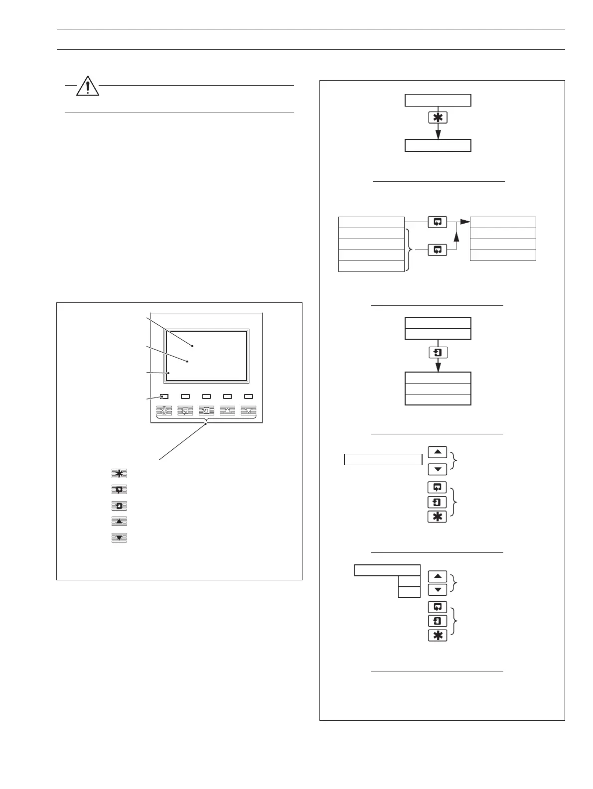
Fig. 2.1 Location of Controls and Displays
Fig. 2.2 Membrane Key Functions
2.1 Powering Up the Monitor
Warning. Ensure all connections are made
correctly, especially to the earth studs – see Section 6.5.
1) Ensure the input sensor(s) is (are) connected correctly.
2) Switch on the power supply to the transmitter. A start-up
screen is displayed while internal checks are performed;
then the Operating Page (Section 2.3) is displayed as the
dissolved organics measuring operation starts.
2.2 Displays and Controls – Fig. 2.1
The upper and center display lines each comprise a 4
1
/2 digit,
7-segment digital display that shows the actual value of the
measured parameter and alarm set points, followed by a
6-character dot matrix display showing the associated units.
The lower line is a 16-character dot matrix display showing
operating and programming information.
2.2.1 Membrane Key Functions – Fig. 2.2
Alarm LEDs
Upper Display Line
Lower Display Line
Membrane Keys
Menu Key
Sidescroll Key
Downscroll Key
Up Key
Down Key
1.25
Diss. Organics
10.25
mg/l C
mg/l C
Center Display Line
B – Advancing to Next Page
C – Moving Between Frames
D – Adjusting and Storing a Parameter Value
E – Selecting and Storing a Parameter Choice
A – Moving Between Menus
For majority
of frames
Frame 1
Frame 2
Frame 3
Frame 4
Page 1
Frame 1
Frame 2
Frame 3
Page 2
Advance to
next page
or
Frame 1
Frame 2
Frame 3
Page X
Frame 4
Advance to
next frame
New value is
stored automatically
Parameter Value
Adjust
Parameter X
Y
Z
Select
New value is
automatically stored
Menu 1
Menu 2
Advance to
next menu
2 OPERATION