42
…6 INSTALLATION
Notes.
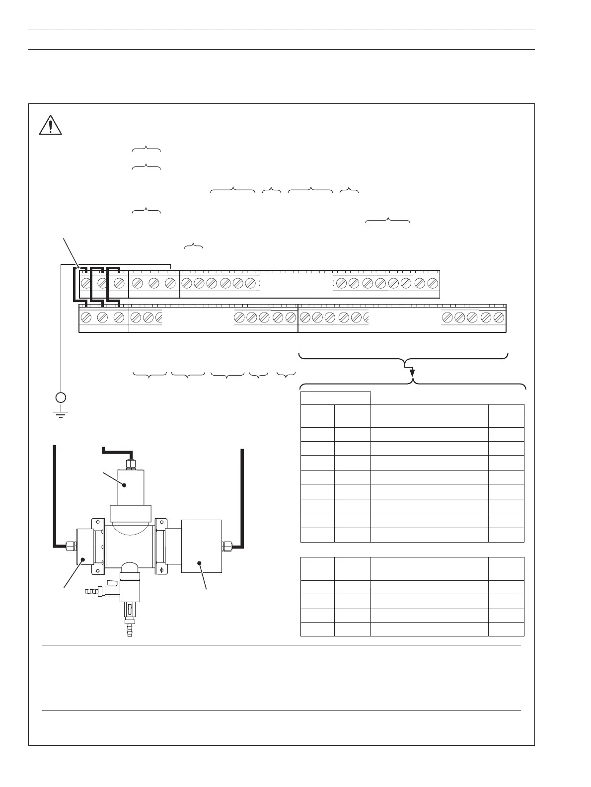
• The screens of the sensor’s emitter, receiver and cleaner cables
must be enclosed in yellow/green sleeving and
connected to the earth (ground) stud fitted to the transmitter case closest to the cable’s entry point – see Fig. 6.10.
• Dual input versions – connect each sensor to the correct input terminals (A or B) as indicated on the sensor's cables.
• Use the three-hole cable gland provided with the sensor for the sensor cables.
Fig. 6.11 Connections
…6.5 Electrical Connections
6.5.4 Connections – Fig. 6.11
L
N
E
CA4
Relay 1 NC A5
NO A6
CA7
Relay 2 NC A8
NO A9
C A10
Relay 3 NC A11
NO A12
Analog Output 1
+ A13
— A14
Analog Output 2
+ A15
— A16
B16
B15
B14
B13
B12
B11
B10
B9
B8
B7
B6
B5
B4
B3
B2
B1
Terminal Block C
C1
Not Used
C2
C3 +12V
C4 Trigger
Sensor A Cleaner
C5 Acknowledge
C6 0V
C7 Out of Sample
Sensor A
C8 Common
Out-of Sample
C9 +12V
C10 Trigger
Sensor B Cleaner
C11 Acknowledge
C12 0V
C13 Out of Sample
Sensor B
C14 Common
Out-of-Sample
C15 TX+
C16 TX—
Digital Communications
C17 RX+
C18 RX–
C19 Common
C20 Not Used
L
N
E
L Line
N Neutral
E Connect supply earth to stud on case
85 to
265 V AC
Receiver
Module
Emitter
Module
Cleaner Module
7320 100 Sensor
Factory-fitted Links.
DO NOT REMOVE
+ve
–ve
24 V DC
Terminal Block B
Terminal Block B
Flowcell Connections
Sensor
B
Sensor
A
B1 B9 Emitter 0V
B2 B10 Red
B3 B11 Green
B4 B12
Yellow
B5 B13 Red
B6 B14 Blue
B7 B15 Green
B8 B16
Yellow
Cable
Colors
Blue
Emitter +24V
Emitter Trigger –ve
Emitter Trigger +ve
Receiver +12V
Receiver 0V
Receiver Reference Signal
Receiver UV Signal
Terminal Block C
Flowcell Connections
Sensor
B
Sensor
A
Cable
Colors
C9 C3 Cleaner +12V
C10 C4 Green
C12 C6
Blue
Red
Cleaner Trigger
Cleaner 0V
C11 C5
Acknowledge
Yellow
Terminal Block A
Before making
any electrical
connections,
refer to the
Warnings on
page 36
Earth (Ground)
Stud on Case
(see Fig. 6.10)