34
…6 INSTALLATION
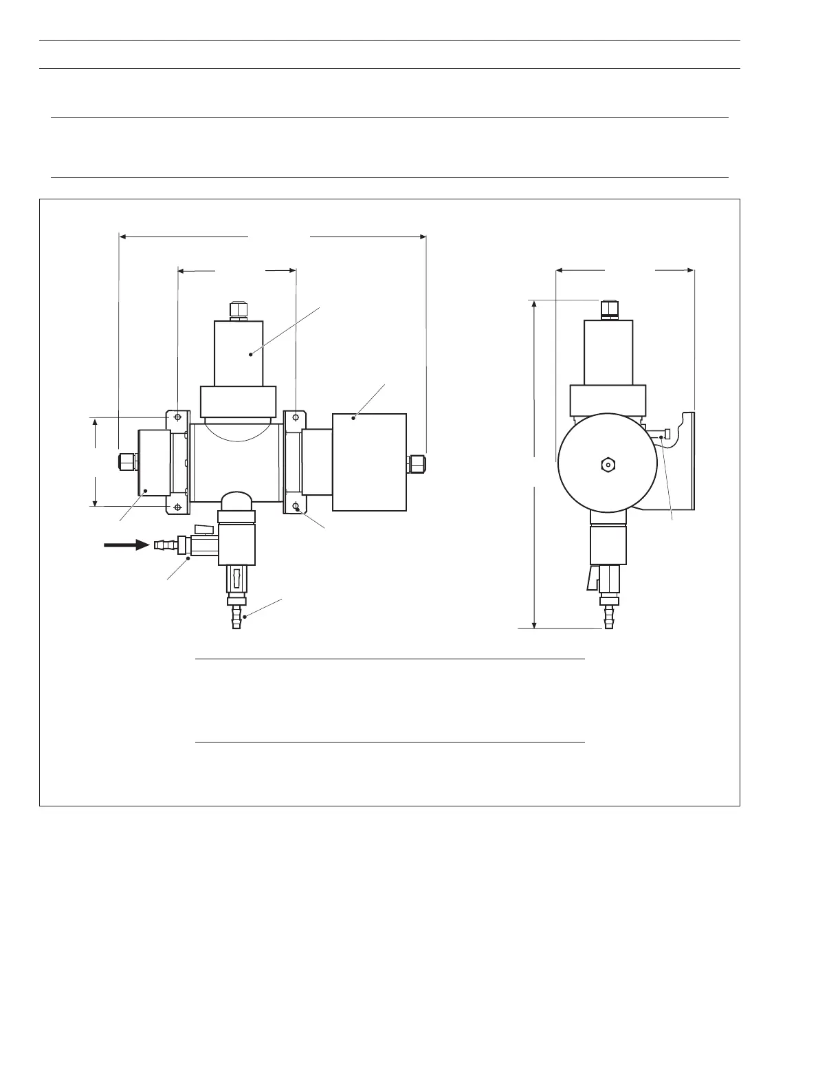
Fig. 6.4 7320 100 Low Range Sensor – Overall Dimensions and Mounting Details
6.3 Installing the Sensor – Figs. 6.4 and 6.5
Notes.
• Use flexible plastic or rigid PVC, polypropylene or metal connecting pipework, depending on the installation.
• Fit isolating valves to enable removal of the sensor.
Dimensions in mm (in.)
Note. For maintenance purposes, allow the following minimum
clearances around the sensor:
Left (for receiver module removal) – 100 mm (3.94 in.)
Right (for emitter module removal) – 100 mm (3.94 in.)
Top (for cleaner module removal) – 200 mm (7.87 in.)
410
(16.14)
327 (12.87)
155 (6.1)
between
centers
118
(4.64)
162 (6.3)
Four holes ø6 (0.24)
for mounting
Sample Inlet
(12 i.d. [0.47] flexible
hose connection)
Drain
(12 i.d. [0.47] flexible
hose connection)
Sample Outlet
(6 [0.24] i.d.
tube connection)
Cleaner Module
Receiver Module
Emitter Module