35
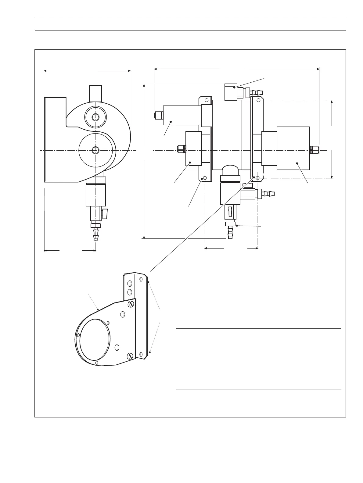
Fig. 6.5 7320 200 High Range Sensor – Overall Dimensions and Mounting Details
405 (15.9)
Emitter ModuleReceiver Module
Cleaner Module
Standard Solution
Filler
4 holes ø6 (0.24)
for mounting
Sample Outlet
(8 [0.3] i.d. tube)
155 (6.1)
between
centers
162 (6.4)
between
centers
Drain
(12 [0.47] i.d. flexible
hose connection)
Sample Inlet
(12 [0.47] i.d. flexible
hose connection)
Fix to wall
Bracket fixed to
flowcell cover,
emitter side
110 (4.3)
191 (7.52)
373
(14.7)
Dimensions in mm (in.)
Notes.
• The emitter end mounting bracket is in two parts to facilitate
emitter module removal during maintenance – see Section 7.
• For maintenance purposes, allow the following minimum
clearances around the sensor:
Left (for receiver module removal) – 150mm (5.9 in.)
Right (for emitter module removal) – 100mm (3.94 in.)
Top (for cleaner module removal) – 200mm (7.87 in.)
6 INSTALLATION…
…6.3 Installing the Sensor – Figs. 6.4 and 6.5