60
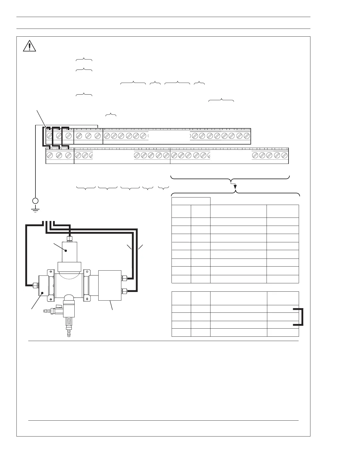
APPENDIX A REPLACING A 7320 TRANSMITTER WITH AN AV400
L
N
E
CA4
Relay 1 NC A5
NO A6
CA7
Relay 2 NC A8
NO A9
C A10
Relay 3 NC A11
NO A12
Analog Output 1
+ A13
— A14
Analog Output 2
+ A15
— A16
B16
B15
B14
B13
B12
B11
B10
B9
B8
B7
B6
B5
B4
B3
B2
B1
Terminal Block C
C1
Not Used
C2
C3 +12V
C4 Trigger
Sensor A Cleaner
C5 Acknowledge
C6 0V
C7 Out of Sample
Sensor A
C8 Common
Out-of Sample
C9 +12V
C10 Trigger
Sensor B Cleaner
C11 Acknowledge
C12 0V
C13 Out of Sample
Sensor B
C14 Common
Out-of-Sample
C15 TX+
C16 TX—
Digital Communications
C17 RX+
C18 RX–
C19 Common
C20 Not Used
L
N
E
L Line
N Neutral
E Connect supply earth to stud on case
85 to
265 V AC
Receiver Emitter
Cleaner
7320 100 Sensor
Factory-fitted Links.
DO NOT REMOVE
+ve
–ve
24 V DC
Terminal Block B
Terminal Block B
Flowcell Connections
Sensor
B
Sensor
A
B1 B9 Emitter 0V
B2 B10 Red (Cable 2)
B3 B11 Green (Cable 1)
B4 B12
Yellow (Cable 1)
B5 B13 Red
B6 B14 Blue
B7 B15 Green
B8 B16
Yellow
Cable
Colors
Blue (Cable 2)
Emitter +24V
Emitter Trigger –ve
Emitter Trigger +ve
Receiver +12V
Receiver 0V
Receiver Reference Signal
Receiver UV Signal
Terminal Block C
Flowcell Connections
Sensor
B
Sensor
A
Cable
Colors
C9 C3 Cleaner +12V
C10 C4 Green
C12 C6
Blue
Red
Cleaner Trigger
Cleaner 0V
C11 C5
Acknowledge
N/A
Terminal Block A
Cable 1
(2 Wire)
Cable 2
(3 Wire) –
see note 5
Before making
any electrical
connections,
refer to the
Warnings on
page 37
Earth (Ground)
Stud on Case
(see Fig. 6.10)
Notes.
1) The screens of the sensor's emitter, receiver and cleaner cables must be enclosed in yellow/green sleeving and
connected to the earth (groud) stud fitted to the transmitter case closest to the cable's entry point – see Fig A.1.
2) Dual input versions – connect each sensor to the correct input terminals (A or B) as indicated on the sensor's
cables.
3) Use the three-hole cable gland provided with the sensor for the sensor cables.
4) Fit a link between C3 and C5. This stops a false Cleaner Fail messages occuring, as the 7320 system cleaner
module does not generate the Cleaner Acknowledge signal used in the AV400 for the Cleaner Fail Diagnostic.
5) Remove the existing tag from the green wire and fit an eyelet tag. Connect the green wire (Cable 2) to the AV400
Transmitter earth (ground) stud.