AWT420 | UNIVERSAL 4-WIRE, DUAL-INPUT TRANSMITTER | OI/AWT420-EN REV. B
107
Output type
Analog output
Analog control outputs can be assigned to any of the available
analog outputs:
• the control output (0 to 100 %) is scaled linearly between
the electrical range low (0.00 to 22.00 mA) and the
electrical range high (0.00 to 22.00 mA) to generate a
current output level
• electrical range low and electrical range high values can
be set in the analog output configuration
Note. Engineering range, Output type and failure mode
configuration parameters normally associated with an analog
output are not required when a control output is assigned as
the analog output source.
Figure 42 Analog output
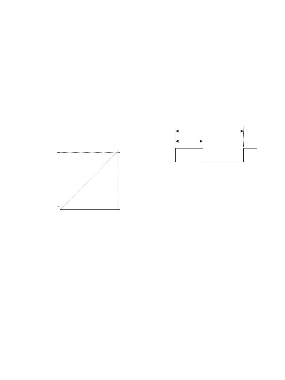
Time proportioning output
Time proportioning control outputs can be assigned to any of
the available relays or digital outputs:
• the control output (0 to 100 %) is scaled linearly between 0
seconds and the configured cycle time (1.0 to 300.0 s) to
generate an ON period
• the relay or digital output is energized for the ON period.
The relay or digital output is de-energized for the
remainder of the cycle time
Figure 43 Analog output
Pulse frequency output
Pulse frequency control outputs can be assigned to any of the
available relays or digital outputs:
• the control output (0 to 100 %) is scaled linearly between 0
and the configured pulse frequency (1 to 120 pulses per
minute) to generate a number of pulses per minute
• the relay or digital output is energized for 300 mS. The
300 mS pulse is repeated at the calculated rate. i.e., the
time between pulses is reduced as the output increases
• the calculated rate is recalculated every second
100 %
Analog
output
Control output
Electrical
range high
Electrical
range low
0 %
Cycle time
ON period

 Loading...


