Chapter 4 – Twelve–Pulse Serial / Sequential Configurations with DCS 600
DCS 600 Manual for 12 – Pulse Operation
II F2
4 - 9
Solution 1
:
SDCS-PIN-51
high-resistance
measurement
[continued]
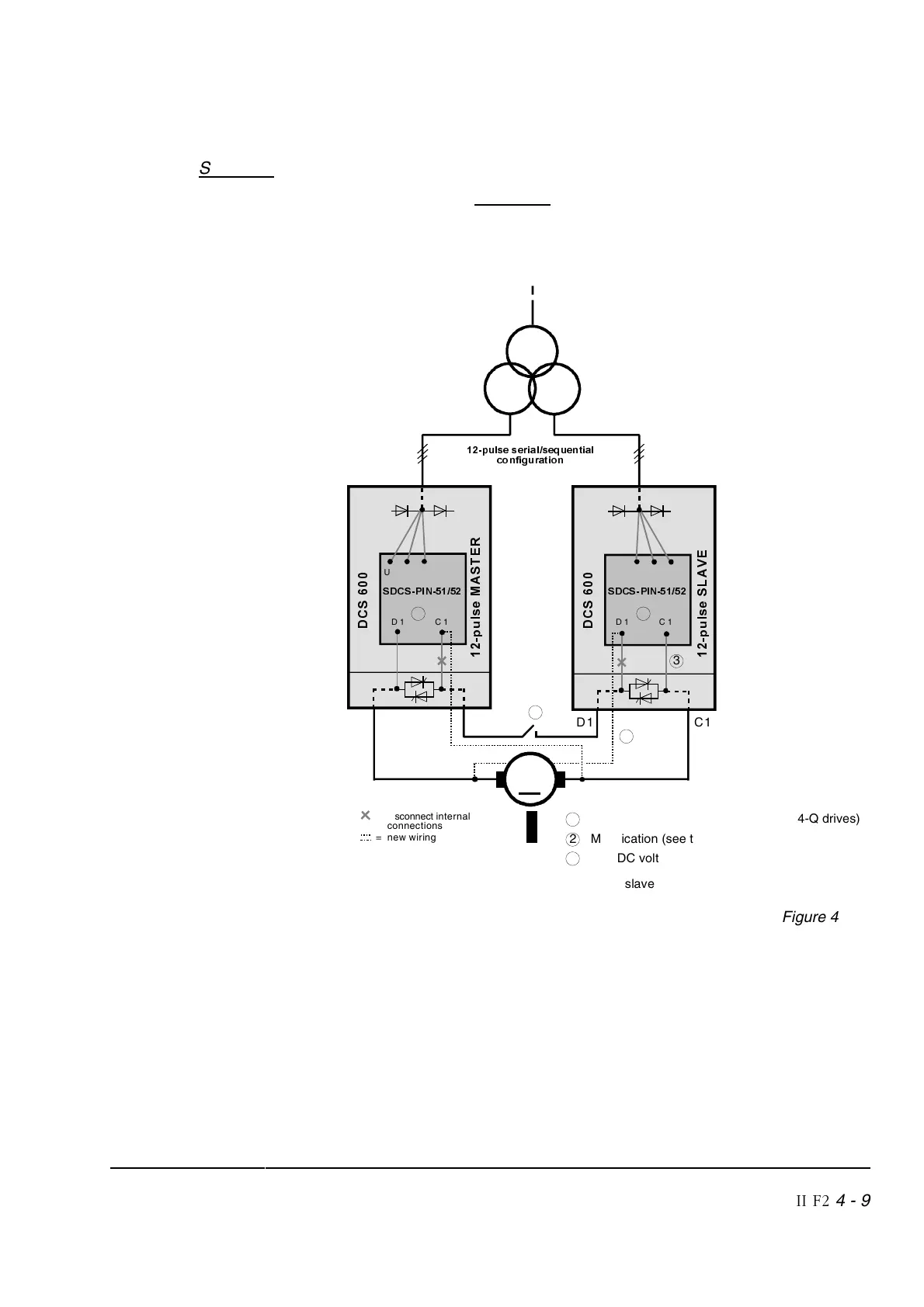
Normal connection with one common DC motor:
Figure 4/3 shows Solution 1 with the required connections for
SDCS-PIN-51 high-resistance measurement.
The correct EMF feedback is selected by the parameter
ADJ UDC
(47.10) = [0,5].
C1
D1
∆
<
SXOVHVHULDOVHTXHQWLDO
FRQILJXUDWLRQ
'
&
6
S
X
O
V
H
0
$
6
7
(
5
=
disconnect
internal
connections
= new wiring
D 1 C 1
6'&63,1
C1
D1
S
X
O
V
H
6
/
$
9
(
D 1 C 1
U 1 V 1 W 1
U 1 V 1
W 1
'
&
6
2
1
1 High-speed DC breaker (required for 4-Q drives)
2 Modification (see table page 4-8)
2
6'&63,1
3
0
3 This DC voltage measurement channel is only
used for single six pulse emergency operation
of the slave
3
Figure 4/3