26
Hardware
3ADW000197R0101 DCS800-R Sel e a
Interface board SDCS-REB-1
Using SDCS-REB-1 plugged to SDCS-PIN-51 the firing commands are arranged in
such a manner, that one SDCS-PIN-48 gives firing pulses to the six forward bridge
thyristors and another one to the six reverse bridge thyristors.
If the REB-1 is plugged on SDCS-PIN-51 board connectors X513, X113 and X213,
the board routes the firing pulse so that the pulse transformer board for the forward
bridge is connected to X613 and the pulse transformer board for the reverse bridge
is connected to X713.
Thyristors in old bridges are often differently positioned on the heat sink than in
modern converter modules. At the bigger standard DCS800 modules firing com-
mands are arranged on the pulse transformer board SDCS-PIN-48.
In this way three channels are used for forward bridge and three channels for re-
verse bridge. This solution keeps the gate leads as short as possible (see chapter
Interfacing the Electronics and Thyristors).
SDCS-REB-1
X213
X713
X113
X613
X513
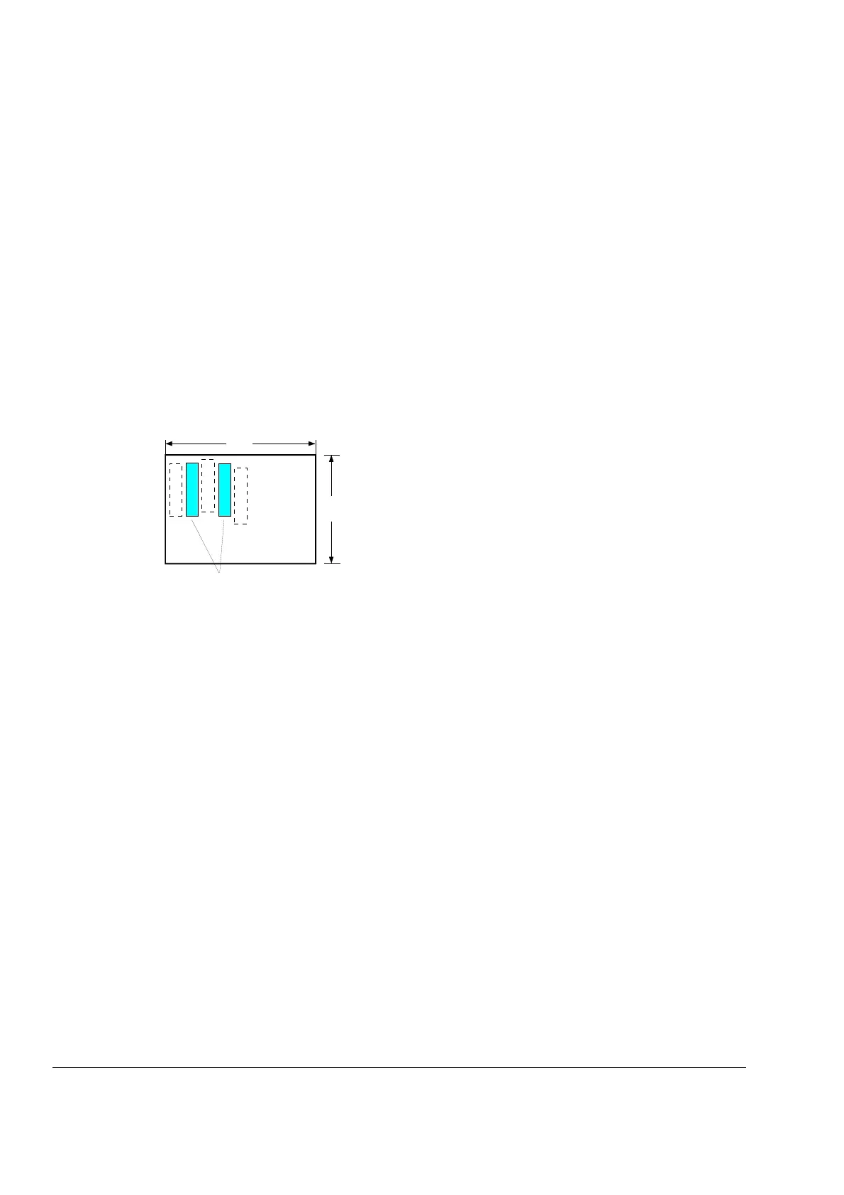
70
50
front side of the board
Layout of the SDCS-REB-1 board