36
Interfacing the Electronics and Thyristors
3ADW000197R0101 DCS800-R Sel e a
Connection for 4-quadrant application – No parallel Thyristors
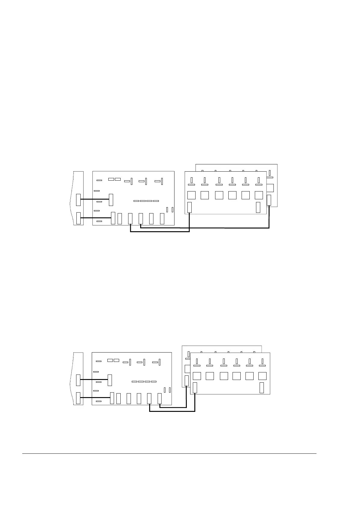
There are three ways shown on the next three figures, how to connect the thyris-
tors, the pulse transformer board(s) and the measuring board to each other.
At figure below the flat cables are connected between
SDCS-PIN-51 X113 to SDCS-PIN-48 X113 and
SDCS-PIN-51 X213 to SDCS-PIN-48 X213,
which gives the result, that
- one SDCS-PIN-48 board transfers all the firing pulses for the thyristors, con-
nected to D1 (see figure Arrangement of thyristors in an anti parallel bridge)
- the other SDCS-PIN-48 board transfers all the firing pulses for the thyristors,
connected to C1 (see figure Arrangement of thyristors in an anti parallel bridge)
X11 3
SDCS-PIN-48
G
C
G
C
G
C
G
C
G
C
G
C
T4 T1 T6 T3 T2
V24
SDCS-PIN-48
U1
SDCS-PIN-51
SDCS-CON-4
V1
W1
C1
D1
X22 X122 X23 X24 X25
X12 S
X13 S
X413 S
X313 S
X13
X513
X113
X213
X413
X313
S2
S1
BCDEF
X113
C
G
C
G
C
G
C
G
C
G
C
G
V11 V26 V13 V22 V15
X213
A
X13 X12
X12
V25 V12 V23 V16 V21 V14
F
X213
4q_c3a_c.dsf
Firing pulse assignment
At figure below the flat cables are connected between
SDCS-PIN-51 X413 to SDCS-PIN-48 X113 and
SDCS-PIN-51 X313 to SDCS-PIN-48 X113,
which gives the result, that
- one SDCS-PIN-48 board transfers all the firing pulses for the thyristors, con-
nected to phase L1 and half of the thyristors, connected to phase L2 (see fig-
ure Arrangement of thyristors in an anti parallel bridge)
- the other SDCS-PIN-48 board transfers all the firing pulses for the rest of the
thyristors, connected to phase L2 and for the thyristors, connected to phase L3
(see figure Arrangement of thyristors in an anti parallel bridge)
X213
SDCS-PIN-48
G
C
G
C
G
C
G
C
G
C
T1 T6 T3 T2 T5
V23
SDCS-PIN-48
BCDEF
X113
C
G
C
G
C
G
C
G
C
G
C
G
V13 V22 V12 V25 V15
X213
A
U1
SDCS-PIN-51
SDCS-CON-4
V1
W1
C1
D1
X22 X122 X23 X24 X25
X12 S
X13 S
X413 S
X313 S
X13
X513
X113
X213
X413
X313
S2
S1
X13 X12
X12
A
C
G
V24 V14 V21 V11 V26 V16
X113
4q_c4a_b.dsf
Firing pulse assignment