35
Interfacing the Electronics and Thyristors
3ADW000197R0101 DCS800-R Sel e a
Interfacing the Electronics and Thyristors
There are several ways to connect the firing commands from the measurement
board to the pulse transformer board(s). The assignment of power section, mains
connection and wiring to the SDCS-PIN-51 board is mandatory, since the com-
puter board uses this assignment as the basis for computing the pulse sequence.
With existing systems, we recommend following our configuration when numbering
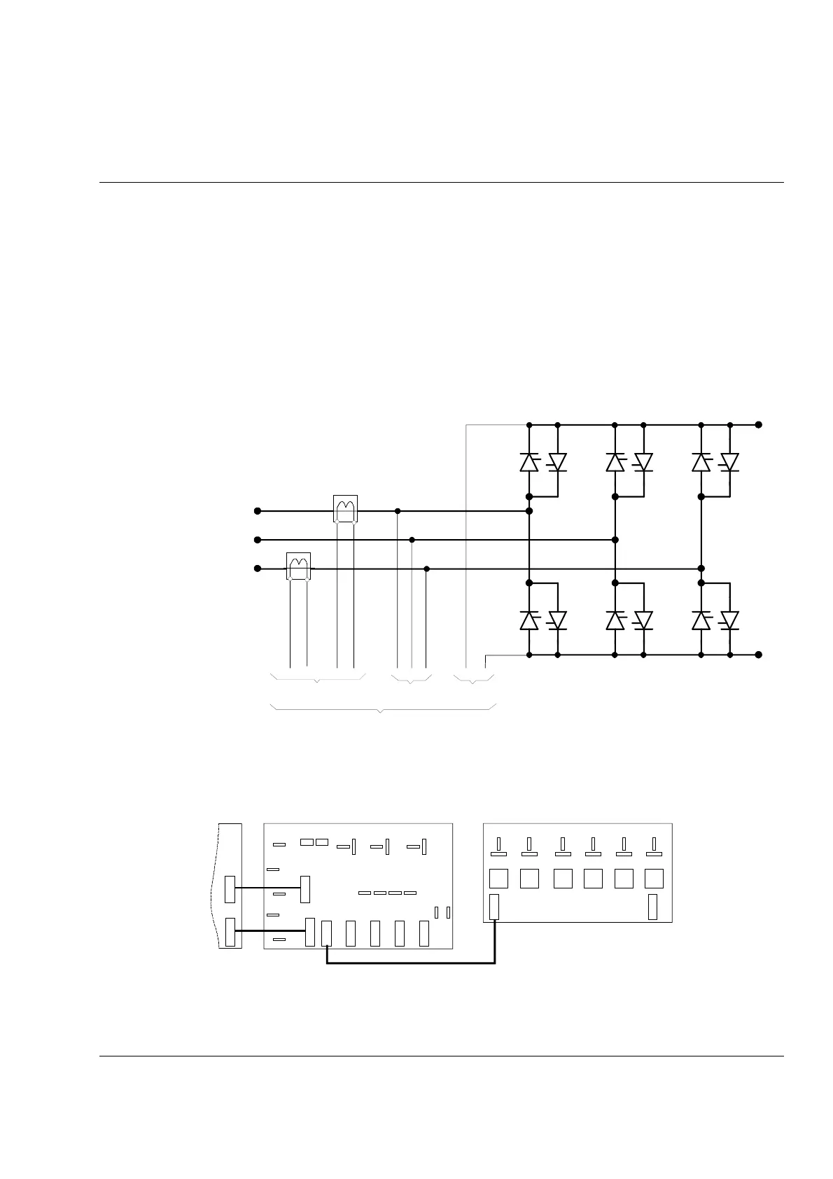
the semiconductor valves so as to preclude any errors. The arrangement of the
thyristors in an anti parallel bridge is presented in the figure below. Thyristors for
forward bridge (current direction 1; SR1) are numbered V11, V12...V16 and thyris-
tors for reverse bridge (current direction 2; SR2) are numbered V21, V22...V26.
In two quadrant applications only the forward bridge is existing.
A
B
ba
A
B
ba
I actual
(L1) U1
(L2) V1
(L3) W1
V14 V21 V16 V23 V12 V25
D1
(-)
V11 V24 V13 V26 V15 V22
C1
(+)
DCS800 u i meas val.dsf
U
AC
actual U
DC
actual
to SDCS-PIN-51
Arrangement of thyristors in an anti parallel bridge
Connection for 2-quadrant application – No parallel Thyristors
V14
SDCS-PIN-48
U1
SDCS-PIN-51
SDCS-CON-4
V1
W1
C1
D1
X22 X122 X23 X24 X25
X12 S
X13 S
X413 S
X313 S
X13
X513
X113
X213
X413
X313
S2
S1
BCDEF
X113
C
G
C
G
C
G
C
G
C
G
C
G
V11 V16 V13 V12 V15
X213
A
X13 X12
X12
2q_c34_c.dsf
2-quadrant application, no parallel connected thyristors