EL3000 CONTINUOUS GAS ANALYZERS | OI/EL3000-EN REV. D 95
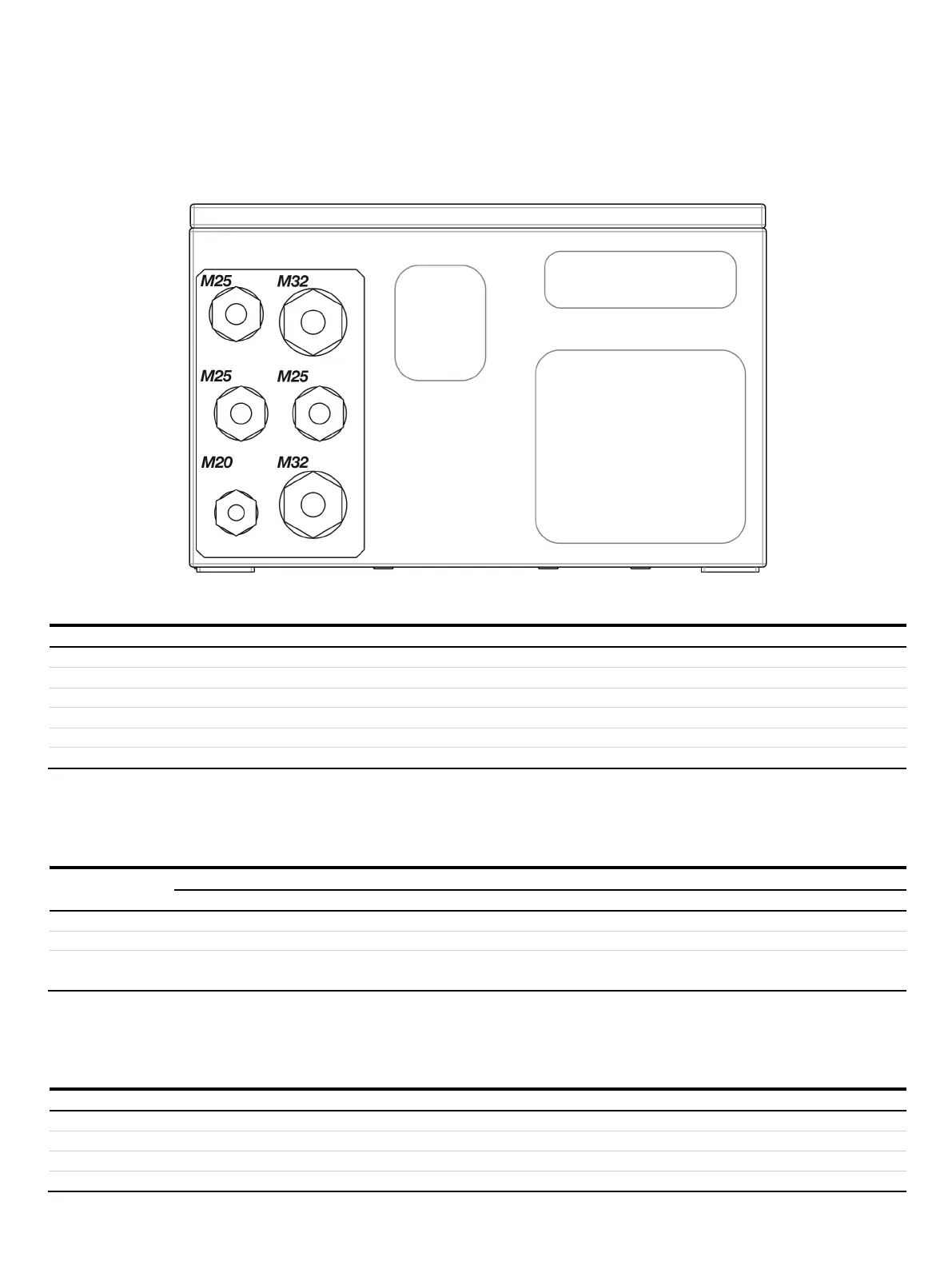
Figure 41: Cable glands model EL3040
Application (recommended)
Permissible cable diameter
to 13 mm
8 to 17 mm (insert 5 × 4 mm)
to 17 mm
8 to 17 mm (insert 3 × 7 mm)
to 21 mm
Cable glands for use in potentially explosive atmospheres
During installation, the clamping range for lines as well as the tightening torques of the cable glands must be observed. The cable
glands have several gasket rings which need to be removed as needed depending on the cable diameter.
Clamping range for lines and tightening torque
—
mm / 3.0 Nm
mm / 4.0 Nm
mm / 1.5 Nm
mm / 1.3 Nm
—
mm / 2.0 Nm
mm / 2.0 Nm
Note
Only suited and cable glands and reduction nozzles approved for the Ex Zone may be used as spare parts.
• The use of other cable glands and blind plugs lead to a loss of Ex-approval!
Specifications for the selection of cable glands
Thread sizes in the connection box
M20×1.5; M32×1.5; M25×1.5
Gasketing via sprayed-on sealing ring on the contact surface of the cable gland
Maximum surface roughness of the connection box
Wall thickness range of the connection box
4 to 5 mm