Operation Manual / 4 Product description / A100-M axial
Page 15 /
© Copyright 2016 ABB. All rights reserved.
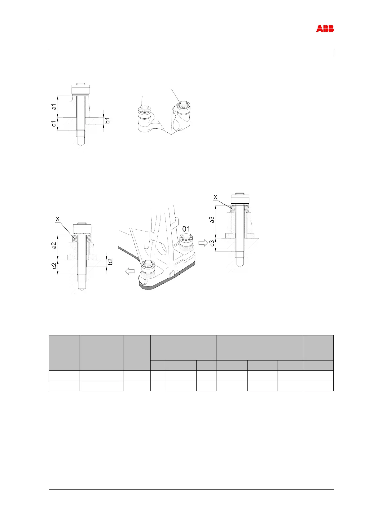
Figure 11: Compressor-end foot
Figure 12: Turbine-end foot
Screw dimensions and number of cup springs
A175-M M36 10.9 95 ø38x31 85 113 / 148
ø38x12 66 / 54 11
Table 3: Foot bolt dimensions
Holes b1/b2 are needed to achieve the required clamping length. An additional drill hole is not
needed at the higher turbine-end foot side (01).