Operation Manual / A130-M.. - A145-M..
3 Removing and Installing / 3.3 Installing the turbocharger
© Copyright 2022 ABB. All rights reserved. HZTL4031_EN Rev.P February 2022
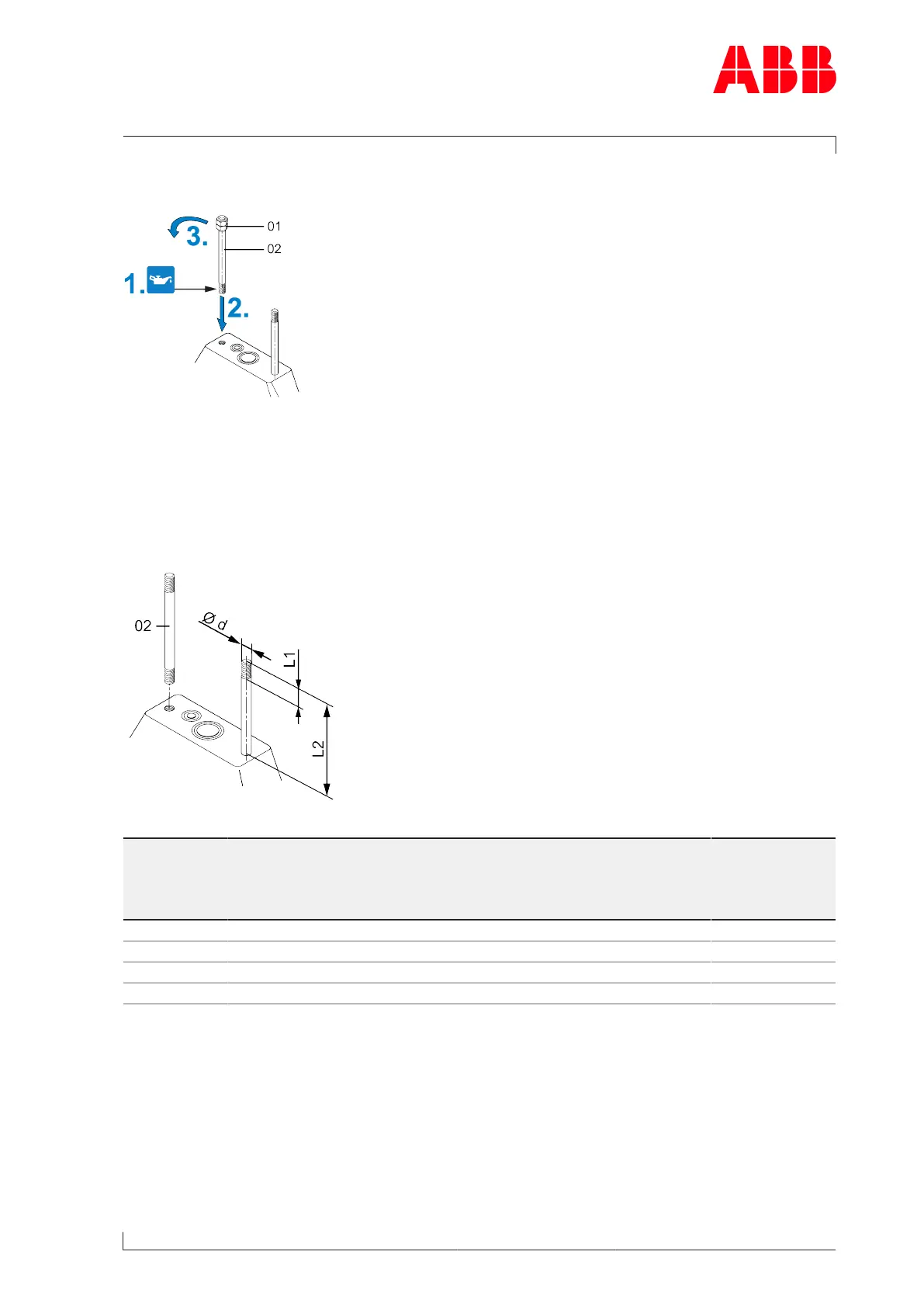
3.3.2 Fitting threaded rods
Fig.18: Fitting threaded rods onto the bracket
1. Lightly oil the surfaces of the threaded rods(02) to be screwed in.
2. Screw the threaded rods into the bracket with the aid of locknuts(01).
3. Remove nuts(01) again.
Requirements for the threaded rods
Fig.19: Requirements for threaded rods
Product Diameter
Threaded rod
[mm]
Material
DIN / ISO 898
(Part 1)
Thread length
L1[mm]
Oil-cooled
L2 [mm]
Water-cooled
L2 [mm]
A130 Ø 16 / M16 10.9 / 12.9 ≥ 30 250 250
A135 Ø 20 / M20 10.9 / 12.9 ≥ 30 270 325
A140 Ø 24 / M24 10.9 / 12.9 ≥ 70 350 … 360 410 … 420
A145 Ø 30 / M30 10.9 / 12.9 ≥ 80 415 … 425 --
Table5: Requirements for threaded rods
The threaded rods and nuts for fastening the turbocharger on the bracket are not included
in the Turbo Systems scope of delivery. The clamping nuts are included in the Turbo Systems
scope of delivery.
Page 37 / 149