EasyManua.ls Logo

ABB i-bus KNX - Connection Diagram (Thermoelectric, PWM)

ABB i-bus KNX
264 pages
Print Icon
To Next Page IconTo Next Page
To Previous Page IconTo Previous Page
Loading...
ABB i-bus
®
KNX
Device technology
32 2CDC508134D0202 | FCA/S 1.x.x.1
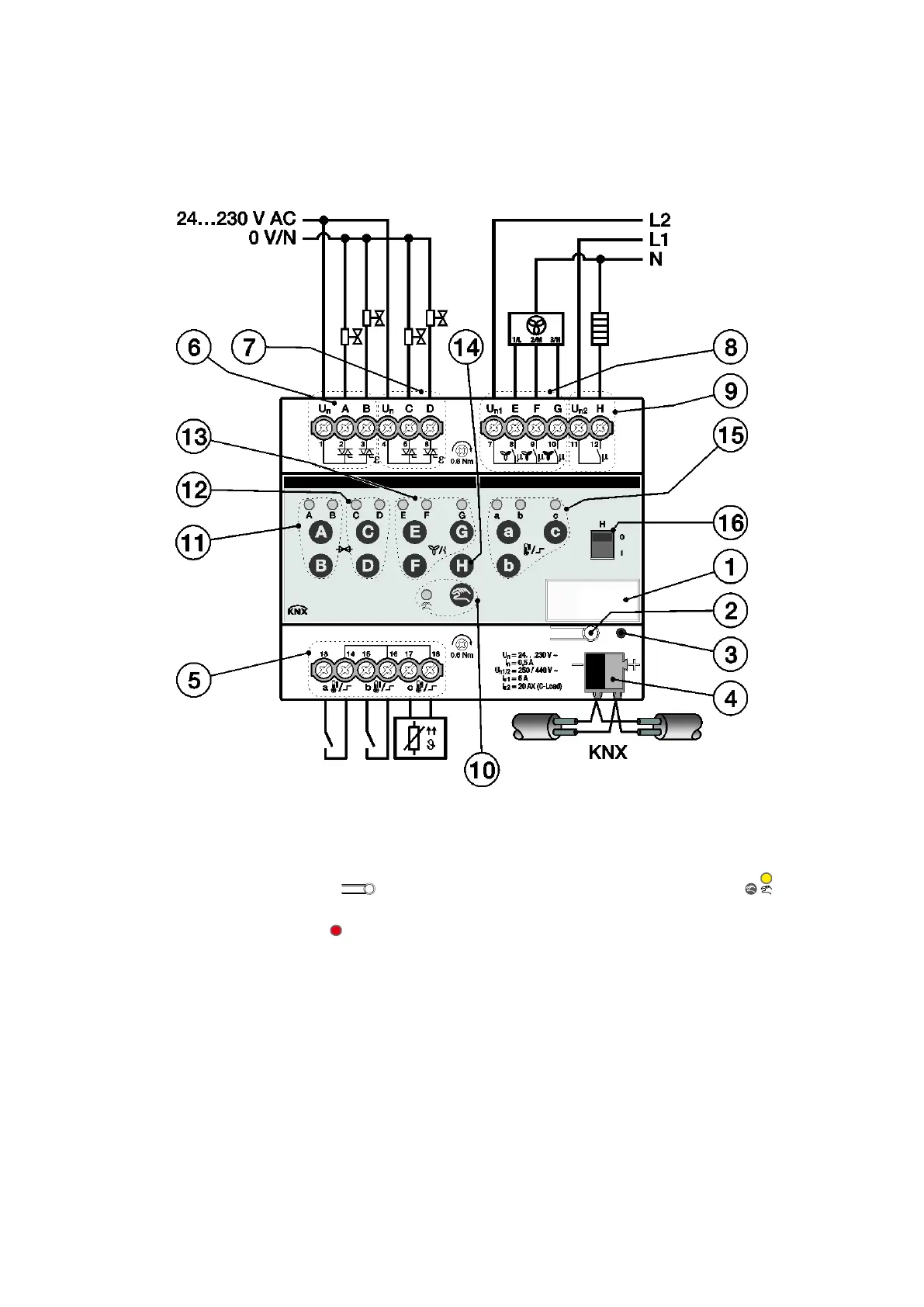
2.2.11 Connection diagram (thermoelectric, PWM)
FCA/S 1.1.2.2
1
Label carrier
9
Output H
2
Programming button
10
Manual operation button/LED (yellow)
3
Programming LED (red)
11
Valve output A/B buttons/LEDs
(e.g. heating) (yellow)
4
Bus connection terminal
12
Valve output C/D buttons/LEDs
(e.g. cooling) (yellow)
5
Inputs a, b, c
13
Output E, F, G button/LEDs
fan speed 1, 2, 3 (yellow)
6
Valve output A/B (e.g. heating)
14
Output H button
7
Valve output C/D (e.g. cooling)
15
Inputs a, b, c buttons/LEDs (yellow)
8
Fan
16
Output H display
2CDC072015F0015

Table of Contents

Related product manuals