ABB i-bus
®
KNX
Device technology
62 2CDC508134D0202 | FCA/S 1.x.x.1
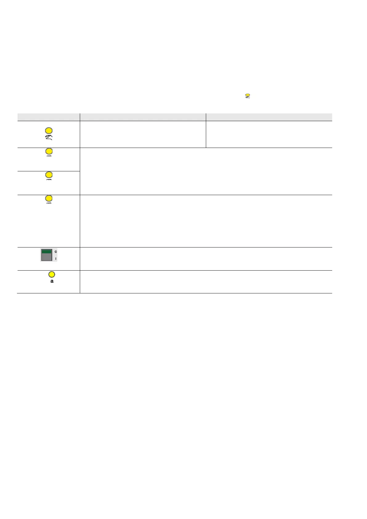
2.6.1 Display elements
Indicator LEDs are located on the front of the device.
All LEDs Output X indicate the current state. In KNX operation the LED is off.
The response of the display elements is described in the following table:
Off: The device is in KNX operation
Flashing: Changeover to Manual operation.
On: The device is in Manual operation
Flashing: Changeover to KNX operation.
On: Control ≠ 0
Off: Control = 0
Flashing: Both LEDs (A+B or C+D) of an output flash in the event of overload/short circuit (frequency 4.8 Hz).
Flashing: Both LEDs (A+B or C+D) of an output flash quickly simultaneously in the event of an adjustment (frequency
1.2 Hz).
With a state change the new state is immediately indicated.
As switch actuator:
0: Contact open
1: Contact closed
As fan:
On: E: Fan speed 1; F: Fan speed 2; G: Fan speed 3
Off: Fan is off.
0: Contact open
1: Contact closed
Send as switch sensor and value:
On: Input closed
Off: Input open