1 Description
1.6.1 Introduction
3HAC9117-1 Rev.N 35
1.6 Mounting equipment
1.6.1 Introduction
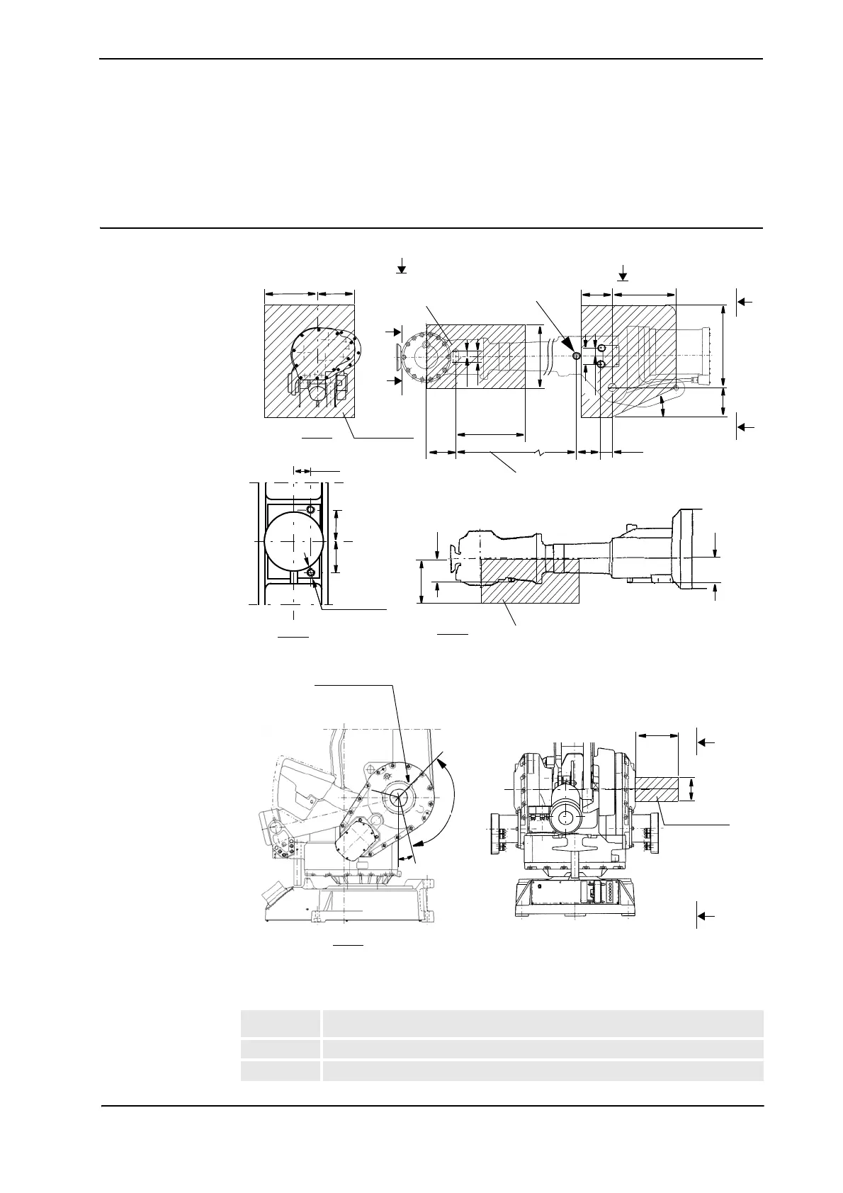
IRB 4400/45, IRB 4400/60, IRB 4400/L30 and IRB 4450/S
Figure 19 The shaded area indicates the permitted positions (center of gravity) for any extra equipment
mounted in the holes (dimensions in mm).
Pos Description
A M8 (2x) Used if option 218-6 is chosen, Depth of thread 9
B M8 (3x) Depth of thread 14
200
110
106
144
115
25
50
77
38.5
300
340
150
300
150
390
20
o
B
B
B - B
A
A - A
250
175
A
Max. 15 kg
54
D - D
D
D
15
29.5
29.5
120
o
(3x)
15
o
C - C
C
C
D=100
195
(A)
(B)
(C)
(D)
(E)
(F)
(G)