66 Electrical design and installation Manual Power Quality Filter PQFS
For cabling the digital output contacts to monitor other filter operation, the same
approach as shown in Figure 44 can be adopted. The electrical characteristics of the
digital output contacts and the points to pay attention to are discussed in Section 6.12.2.
In order to obtain full redundancy with filters consisting of more than one master unit,
the digital outputs of all the units in a multi-master arrangement have to be set up and
cabled in the same way. The wiring diagram given in Figure 45 can be used to implement
the monitoring of these functions in multi-master units.
6.12.5 Cabling of main/auxiliary control functionality
The active filter features main and auxiliary control setup modes. This implies that two
different compensation characteristics can be defined, e.g. one for the day and one for
the night or one for normal network operation and one for backup generator operation.
With the PQF-Manager a set up can be made to either use always the main or the auxiliary
settings. In addition, the possibility exists to switch between main and auxiliary settings
‘automatically’ according to a signal applied to a digital input of the PQF-Manager (Cf.
Figure 39). Any digital input can be configured to act as the deciding factor for switching
between the main and auxiliary settings. Moreover, both normal and inverse logic can be
used to drive the digital inputs.
Note that in a multi-unit filter system in which more than one master system is present,
the digital inputs of all masters have to be set up and cabled in the same way to obtain
full redundancy.
The electrical requirements of the digital inputs are as discussed in Chapter 12.
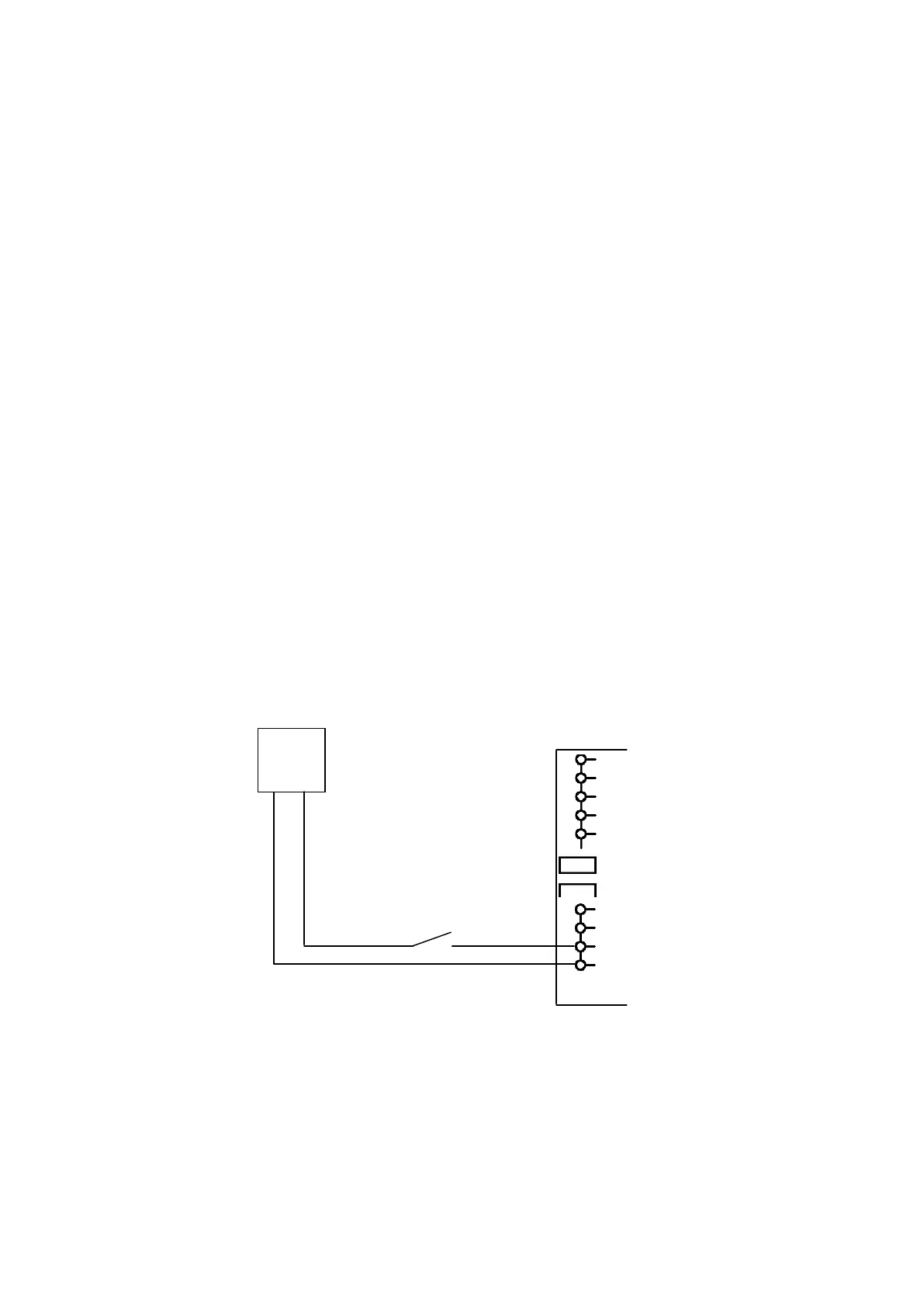
Figure 46 gives an example of how to implement the main/auxiliary control switching
functionality on Digital Input 2. It is assumed that normal control logic is used.
External switch for
switching between main
and auxiliary filter settings
Digital input 2
(15-24Vdc)
Remark:
(a)
Left hand terminal block when looking from rear, counting from top to bottom
Figure 46: Example of how to cable the 2
nd
digital input of the PQF-Manager for main/auxiliary
control switching functionality
When implementing the function described above, please note that according to the
setup done with the PQF-Manager for the input considered, the filter may behave
differently. Table 29 shows the filter behavior as a function of the PQF-Manager settings.