EasyManuals Logo

ABB PQFS User Manual

ABB PQFS
214 pages
To Next Page IconTo Next Page
To Previous Page IconTo Previous Page
Page #16 background imageLoading...
Page #16 background image
16 Hardware description  Manual Power Quality Filter PQFS
Up to 8 PQFS master panels can be connected in parallel providing full redundancy to the
customer. In addition to using master panels only, PQFS units can be connected in a
master-slave arrangement.
4.3 The PQF current generator hardware
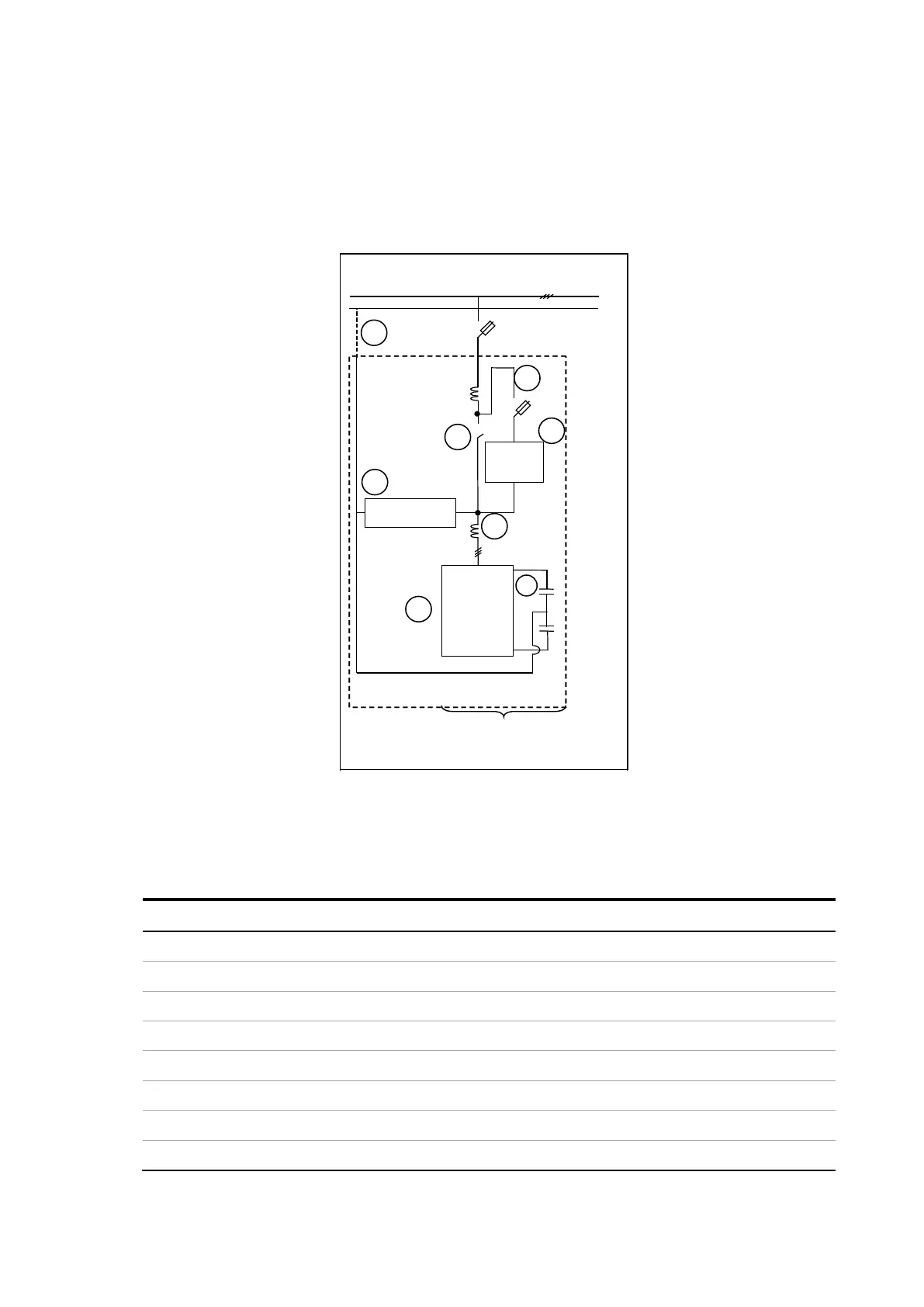
The power circuit of a PQFS unit is represented hereafter.
N
Preload
resistor
Output filter
IGBT
Inverter
Master Unit
N
AC power supply
L
L
1
2
3
4
5
6
7
8
Figure 10: Power circuit diagram of a PQFS active filter
The description of the main components is given in Table 5.
Table 5: Main components of a PQFS active filter
Item Main components
1
IGBT inverter
2 DC bus capacitors
3 PWM reactor
4
Output filter
5
Preload resistor
6
Main contactor
7 Auxiliary fuses
8 Neutral cable connection (not mandatory)

Table of Contents

Questions and Answers:

Question and Answer IconNeed help?

Do you have a question about the ABB PQFS and is the answer not in the manual?

ABB PQFS Specifications

General IconGeneral
BrandABB
ModelPQFS
CategoryIndustrial Electrical
LanguageEnglish

Related product manuals